
Installation Manual
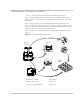
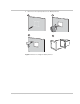
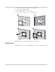
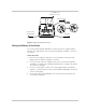
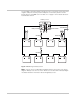
Table Of Contents
2-18 975-0691-01-01 Revision B
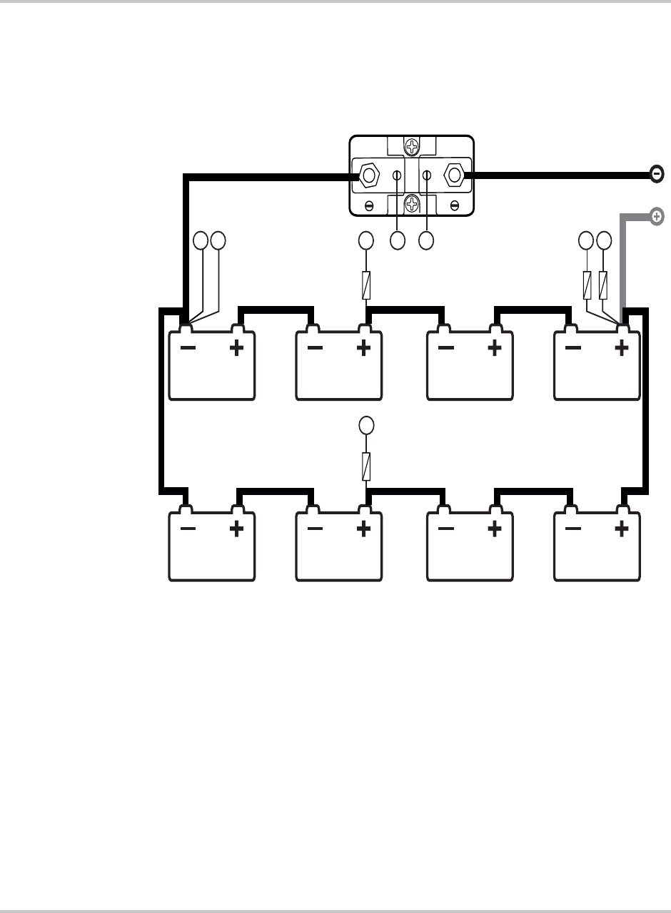
The included in-line 2AT voltage-sensing fuses are connected to the positive and
negative endpoints and the positive midpoints of the battery bank as shown
below. Refer to the Label column of Table 2-1 on page 2–19 for details about the
lettered labels below.
Note: Only the fuses included with the Battery Monitor are shown in the above
diagram. Battery fuses are not shown. Refer to the Conext XW+ Inverter/Charger
Installation Guide for information about wiring battery fuses.
SYSTEM
BA
TTE
RY
H FC
D
E
G
A
B
2x 2 fuseAT fuse
AT fuse
To inverter/charge
r
AT2
2
Battery Terminal
System Terminal
Battery Shunt
Figure 2-10 Wiring the battery bank