ConextSW-NA-OwnersGuide.book Page i Thursday, July 23, 2015 3:26 PM Conext™ SW Inverter/Charger Conext SW 2524 120/240 Split-phase (865-2524) Conext SW 4024 120/240 Split-phase (865-4024) Conext SW 4048 120/240 Split-phase (865-4048) Owner’s Guide 975-0638-01-01 Rev E 7-2015 TM solar.schneider-electric.
ConextSW-NA-OwnersGuide.
ConextSW-NA-OwnersGuide.book Page i Thursday, July 23, 2015 3:26 PM Conext SW Inverter/Charger Conext SW 2524 120/240 Split-phase (865-2524) Conext SW 4024 120/240 Split-phase (865-4024) Conext SW 4048 120/240 Split-phase (865-4048) Owner’s Guide solar.schneider-electric.
ConextSW-NA-OwnersGuide.book Page ii Thursday, July 23, 2015 3:26 PM Copyright and Contact Copyright © 2012-2015 Schneider Electric. All Rights Reserved. All trademarks are owned by Schneider Electric Industries SAS or its affiliated companies.
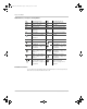
ConextSW-NA-OwnersGuide.book Page iii Thursday, July 23, 2015 3:26 PM About This Guide Purpose The purpose of this Owner’s Guide is to provide explanations and procedures for operating, troubleshooting, and maintaining the Conext SW Inverter/Charger. Scope The Guide provides safety guidelines, as well as information about operating and troubleshooting the unit. It does not provide details about particular brands of batteries. You need to consult individual battery manufacturers for this information.
ConextSW-NA-OwnersGuide.
ConextSW-NA-OwnersGuide.book Page v Thursday, July 23, 2015 3:26 PM Important Safety Instructions READ AND SAVE THESE INSTRUCTIONS - DO NOT DISCARD This guide contains important safety instructions for the Conext SW Inverter/ Charger that must be followed during operation and troubleshooting. Read and keep this Owner’s Guide for future reference. Read these instructions carefully and look at the equipment to become familiar with the device before trying to install, operate, service or maintain it.
ConextSW-NA-OwnersGuide.book Page vi Thursday, July 23, 2015 3:26 PM Safety Safety Information DANGER ELECTRICAL SHOCK AND FIRE HAZARD Installation must be done by qualified personnel to ensure compliance with all applicable installation and electrical codes and regulations. Instructions for installing the Conext SW are provided in a separate installation guide for use by qualified installers only. Failure to follow these instructions will result in death or serious injury.
ConextSW-NA-OwnersGuide.book Page vii Thursday, July 23, 2015 3:26 PM Safety DANGER ELECTRIC SHOCK HAZARD • For indoor use only. This inverter/charger is designed for off-grid, solar, backup, and hybrid applications. See the installation guide for information. • Do not operate the inverter/charger if it has been damaged in any way. • Do not operate the inverter/charger with damaged or substandard wiring.
ConextSW-NA-OwnersGuide.book Page viii Thursday, July 23, 2015 3:26 PM Safety Precautions When Working With Batteries IMPORTANT: Battery work and maintenance must be done by qualified personnel knowledgeable about batteries to ensure compliance with battery handling and maintenance safety precautions. WARNING BURN AND FIRE HAZARD • Always wear proper, non-absorbent gloves, complete eye protection, and clothing protection.
ConextSW-NA-OwnersGuide.book Page ix Thursday, July 23, 2015 3:26 PM Safety NOTICE RISK OF INVERTER/CHARGER DAMAGE Do not exceed the maximum inverter load limit (power) on either single phase (L1/N or L2/N). See “Inverter Specifications” on page 6–2. Failure to follow these instructions can result in damage to equipment. NOTICE RISK OF INVERTER/CHARGER DAMAGE Never place the Conext SW Inverter/Charger unit directly above batteries; gases from a battery will corrode and damage the inverter/charger.
ConextSW-NA-OwnersGuide.book Page x Thursday, July 23, 2015 3:26 PM Safety FCC Information to the User This equipment has been tested and found to comply with the limits for a Class B digital device, pursuant to part 15 of the FCC Rules. These limits are designed to provide reasonable protection against harmful interference in a residential installation.
ConextSW-NA-OwnersGuide.
ConextSW-NA-OwnersGuide.
ConextSW-NA-OwnersGuide.
ConextSW-NA-OwnersGuide.
ConextSW-NA-OwnersGuide.
ConextSW-NA-OwnersGuide.
ConextSW-NA-OwnersGuide.
ConextSW-NA-OwnersGuide.
ConextSW-NA-OwnersGuide.book Page 1 Thursday, July 23, 2015 3:26 PM 1 Introduction The following topics will be covered in this chapter.
ConextSW-NA-OwnersGuide.book Page 2 Thursday, July 23, 2015 3:26 PM Introduction Materials List Congratulations on your purchase of the Conext SW Inverter/Charger (called Conext SW). The Conext SW has been designed to give you premium true sine wave power, ease of use, and outstanding reliability for your off-grid and power backup applications.
ConextSW-NA-OwnersGuide.book Page 3 Thursday, July 23, 2015 3:26 PM Key Features Key Features The Conext SW Inverter/Charger is a true sine wave inverter/charger that can be used for off-grid, backup, solar, and hybrid applications. The Conext SW Inverter/ Chargers are designed to operate with a wide variety of generators and are capable of operating in parallel with a generator for short durations to assist with starting large loads.
ConextSW-NA-OwnersGuide.book Page 4 Thursday, July 23, 2015 3:26 PM Introduction Key Features Explained Built-in Charge Formulas For the unit to perform at the highest level, the batteries must be charged correctly. The Conext SW has optimized algorithms for flooded, gel, and AGM batteries.
ConextSW-NA-OwnersGuide.book Page 5 Thursday, July 23, 2015 3:26 PM Basic Protection Features Multiple Unit Charging Two Conext SW Inverter/Chargers synchronize charging stages to ensure efficient charging of the battery bank. When a single unit transitions from bulk to absorption so does the other unit. In absorption, the two units must complete the absorption stage before transitioning to the next stage. Note that the two units do not load share when charging except during the bulk stage.
ConextSW-NA-OwnersGuide.book Page 6 Thursday, July 23, 2015 3:26 PM Introduction Grid-interactive and Other Features Load Shaving Load shaving (Load Shave) allows the Conext SW to support (or assist) the AC source in powering local loads during a defined window of time (LoadShaveStart and LoadShaveStop). See “Time-of-Use Metering” on page 1–7. It allows the inverter to control how much current can be drawn from the AC source.
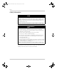
ConextSW-NA-OwnersGuide.book Page 7 Thursday, July 23, 2015 3:26 PM Grid-interactive and Other Features NOTE: Current is regulated by placing a limit (Load Shave Amps) on the current of the AC source. Grid or Generator 10 A AC IN Conext SW 5A 15 A AC OUT AC Loads SCP DC Battery Bank Figure 1-2 Load Shaving in Action Time-of-Use Metering Utilities use time-of-use metering to set utility charges during peak usage hours and to impose a surcharge.
ConextSW-NA-OwnersGuide.book Page 8 Thursday, July 23, 2015 3:26 PM Introduction AC Support allows the Conext SW to support local loads by converting excess power from external DC sources connected to its battery bank. Examples of external DC sources are MPPT solar charge controllers. When local loads demand more energy from the external DC sources then extra current can be pulled in from the AC source as a last resort.
ConextSW-NA-OwnersGuide.book Page 9 Thursday, July 23, 2015 3:26 PM Grid-interactive and Other Features controlled by the MPPT charger so that they can control the state-of-charge of the batteries. AC power from the grid is utilized only when load demand exceeds power available from the MPPT charger for charging and supplying the loads.
ConextSW-NA-OwnersGuide.
ConextSW-NA-OwnersGuide.book Page 11 Thursday, July 23, 2015 3:26 PM Grid-interactive and Other Features < 2 A* Grid NOTE: Entry and exit into AC Support Mode is determined by the battery voltage. In this case, AC support mode is engaged because actual battery voltage is above the AC support voltage level.
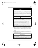
ConextSW-NA-OwnersGuide.book Page 12 Thursday, July 23, 2015 3:26 PM Introduction LOAD SHAVE set start FLOAT starts ABS starts ABS FLOAT FLOAT 2-hour delay starts LOAD SHAVE actual start PLSDelay : : : : : : Figure 1-7 Load Shaving 2-Hour Delay Example The feature also ensures that self-consumption of harvested solar energy is optimized.
ConextSW-NA-OwnersGuide.book Page 13 Thursday, July 23, 2015 3:26 PM Grid-interactive and Other Features Consult the manufacturer's specifications to determine if your PV inverter is compatible with Active Frequency Shift Power Curtailment. Conext SW’s AC coupling function is enabled by default (see “Advanced Features Menu” on page 4–33). NOTICE AC COUPLED PV INVERTER COMPATIBILITY AC power generated by AC coupling PV inverters with Conext SW must be consumed by AC loads or used to charge batteries.
ConextSW-NA-OwnersGuide.book Page 14 Thursday, July 23, 2015 3:26 PM Introduction Low Battery Cut Out Hysteresis Low battery cut out (Low Batt Cut Out) (LBCO) preserves battery life by stopping the inverter when battery voltage drops down to the LBCO value for a few seconds (see LBCO Delay below), then battery charging commences. When charging starts, the voltage level jumps a little but enough that inverting might resume abruptly. Then, battery voltage goes down again and charging starts abruptly.
ConextSW-NA-OwnersGuide.book Page 1 Thursday, July 23, 2015 3:26 PM 2 Components and Mechanical Features The following topics will be covered in this chapter.
ConextSW-NA-OwnersGuide.book Page 2 Thursday, July 23, 2015 3:26 PM Components and Mechanical Features System Components The Conext SW uses Xanbus, a network communications protocol developed to send Conext SW’s operational settings and status to other Xanbus-enabled devices. You can configure and monitor the Conext SW and every Xanbusenabled device in the system using an optional System Control Panel (SCP).
ConextSW-NA-OwnersGuide.book Page 3 Thursday, July 23, 2015 3:26 PM System Components Xanbus-enabled Products and Other Accessories 1 / 6 9 7 10 8 4 11 2 0.9 m cable 7.
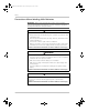
ConextSW-NA-OwnersGuide.book Page 4 Thursday, July 23, 2015 3:26 PM Components and Mechanical Features Conext SW Inverter/Charger Mechanical Features 1 2 TOP TOP 3 7 7 4 6 5 Figure 2-2 Conext SW Front and Side Panels Conext SW Front and Side Panels Before you begin to operate the Conext SW, review the front panel features shown in Figure 2-3 and described in the next table. A detailed view of the lights and buttons on the front panel is also shown.
ConextSW-NA-OwnersGuide.book Page 5 Thursday, July 23, 2015 3:26 PM Conext SW Inverter/Charger Mechanical Features Item Description 4 AC Ground terminals. See “AC and DC Terminals, Network and Communication Ports Panel” on page 2–6. 5 AC line terminals. See “AC and DC Terminals, Network and Communication Ports Panel” on page 2–6. 6 Two variable-speed cooling fans maintain a cool internal temperature of critical components.
ConextSW-NA-OwnersGuide.book Page 6 Thursday, July 23, 2015 3:26 PM Components and Mechanical Features Conext SW AC/DC/Ports Side Panel DANGER ELECTRICAL SHOCK AND FIRE HAZARD Installation must be done by qualified personnel to ensure compliance with all applicable installation and electrical codes and regulations. Instructions for installing the Conext SW are provided in a separate installation guide for use by qualified installers only.
ConextSW-NA-OwnersGuide.book Page 1 Thursday, July 23, 2015 3:26 PM 3 Operation The following topics will be covered in this chapter.
ConextSW-NA-OwnersGuide.book Page 2 Thursday, July 23, 2015 3:26 PM Operation Start Up Behavior When the Conext SW is powered up (energized) or has been reset (using the Reset button on the front panel), all of the front panel LEDs illuminate and remain on for a minimum of five seconds. During this interval, the fans also turn on as the unit executes internal diagnostics.
ConextSW-NA-OwnersGuide.book Page 3 Thursday, July 23, 2015 3:26 PM Inverter Operation Using the Front Panel Inverter Operation Using the Front Panel IMPORTANT: Review the “Important Safety Instructions” on page v before operating the inverter/charger. Once the inverter/charger is installed, you can operate it in invert mode. The steps below will test the unit for normal operation using the front panel. To test the inverter using the front panel: 1.
ConextSW-NA-OwnersGuide.book Page 4 Thursday, July 23, 2015 3:26 PM Operation Table 3-1 Front Panel LEDs Icon LED Status Action (or Status Item) Steady Green If generator or grid AC is unavailable You can run your appliances from the inverter. and operating conditions are met, the Conext SW will produce AC voltage to power loads. Flashing Green The inverter is in AC Support or Load Shave mode. You can run your appliances from the inverter.
ConextSW-NA-OwnersGuide.book Page 5 Thursday, July 23, 2015 3:26 PM Inverter Operation Using the Front Panel Operating Limits for Inverter Operation Temperature The Conext SW series of inverter/chargers will operate at rated power continuously at 77 °F (25 °C) with some models capable of continuous operation at much higher ambient temperature. However, the continuous power rating at elevated ambient temperature may differ between models. See “Environmental Specifications” on page 6–5 for full details.
ConextSW-NA-OwnersGuide.book Page 6 Thursday, July 23, 2015 3:26 PM Operation Battery power during AC bypass When sufficient AC is detected by the inverter/charger and the battery is sufficiently charged, the AC is automatically passed through to the loads. However, if the battery is less than 12 V (for 24-volt models), 24 V (for 48-volt model), or had been disconnected, the inverter/ charger will not pass grid AC through to the loads.
ConextSW-NA-OwnersGuide.book Page 7 Thursday, July 23, 2015 3:26 PM Inverter Operation Using the Front Panel Operating Limits for Charger Operation By default, the maximum charger output current is the rated charger output current for the particular model. Using the SCP, you can reduce the total output if you change the maximum charge rate (Max Chg Rate) on the Conext SW Basic Settings menu or Charger Settings menu under Advanced Settings.
ConextSW-NA-OwnersGuide.book Page 8 Thursday, July 23, 2015 3:26 PM Operation Inverter/Charger Operation using the System Control Panel (SCP) This section contains detailed information and procedures for using your Conext SW in conjunction with the SCP. If you’re using the SCP to operate or monitor the status of the unit, you may also refer to the System Control Panel Owner’s Guide. WARNING LI LIMITATIONS ON USE Do not use in connection with life support systems or other medical equipment.
ConextSW-NA-OwnersGuide.book Page 9 Thursday, July 23, 2015 3:26 PM Inverter/Charger Operation using the System Control Panel (SCP) SCP Features 7 Fault/Warning Standby 1 6 Enter 2 Exit 3 4 5 Feature Description 975-0638-01-01 Rev E 1 Fault/Warning light indicates a device has a fault detection or warning condition and requires attention. The light flashes when a warning occurs and turns on steadily when a fault detection occurs.
ConextSW-NA-OwnersGuide.book Page 10 Thursday, July 23, 2015 3:26 PM Operation Using the Standby Button The Standby button has two functions, depending on how it is pressed. First, when only the Standby button is pressed, it can disable inverting and charging for all Conext SW units in the system. Second, when it is pressed simultaneously with the Exit button, this action puts the entire system into Standby mode.
ConextSW-NA-OwnersGuide.book Page 11 Thursday, July 23, 2015 3:26 PM Inverter/Charger Operation using the System Control Panel (SCP) Viewing the SCP Home Screens The top level screens on the SCP are the Startup screen, the System Status screen, and the Device Home screens. After power is applied and the Startup screen appears, the SCP displays the System Status screen.
ConextSW-NA-OwnersGuide.book Page 12 Thursday, July 23, 2015 3:26 PM Operation IMPORTANT: If you are uncertain which SCP screen or menu you are viewing, you can always return to the starting point—the System Status screen—by pressing Exit repeatedly until the screens stop changing.
ConextSW-NA-OwnersGuide.book Page 13 Thursday, July 23, 2015 3:26 PM Inverter/Charger Operation using the System Control Panel (SCP) Pressing the down arrow button from the Conext SW Home screen displays the Home screens for other Conext SW units and other Xanbus-enabled devices in the system. Table 3-2 Conext SW Home Screen States Conext SW Status Displayed When... Invert The Conext SW is supplying power to loads by inverting power from the batteries.
ConextSW-NA-OwnersGuide.book Page 14 Thursday, July 23, 2015 3:26 PM Operation Viewing Other Screens This section describes the next level of screens and menus on the SCP. Select Device Menu The Select Device menu displays a list of Xanbus-enabled devices in the system, including the Conext SW and the SCP. The Select Device menu is where you can access the Setup menus for each device in the system. The length of the Select Device menu depends on how many Xanbus-enabled devices are installed.
ConextSW-NA-OwnersGuide.book Page 15 Thursday, July 23, 2015 3:26 PM Inverter/Charger Operation using the System Control Panel (SCP) Meters Screen The Meters screen displays total system power production, generator voltage and current status, and load voltage and current status. To view the Meters screen: ◆ On the Conext SW Setup menu highlight Meters, and then press Enter.
ConextSW-NA-OwnersGuide.book Page 16 Thursday, July 23, 2015 3:26 PM Operation Changing Operational Settings The following table shows the various settings you can change to effectively operate the Conext SW inverter/charger. To navigate to the Conext SW Setup menu: 1. From the System Status screen (see 1A), press Enter to view the Select Device menu. Go to step 2. Or From the Conext SW Home screen (see1B), press Enter. The Conext SW Setup menu appears. 2.
ConextSW-NA-OwnersGuide.book Page 17 Thursday, July 23, 2015 3:26 PM Inverter/Charger Operation using the System Control Panel (SCP) Table 3-4 Conext SW Setup menu Menu Item Description Inverter Enables or disables the inverter. See “To change an operational setting” on page 3–18. NOTE: When changing the operational setting for Inverter, remember that enabling the inverter is not the same as the inverter being turned on.
ConextSW-NA-OwnersGuide.
ConextSW-NA-OwnersGuide.book Page 1 Thursday, July 23, 2015 3:26 PM 4 Configuration via SCP The following topics will be covered in this chapter.
ConextSW-NA-OwnersGuide.book Page 2 Thursday, July 23, 2015 3:26 PM Configuration via SCP Viewing the Firmware Revision Number You may need to view the firmware revision number (F/W Rev.) of the Conext SW when troubleshooting the unit with authorized service personnel. To view the firmware revision number: 1. From the System Status screen, press the Enter button. The Select Device menu screen appears. 2. From the Select Device screen, press the Enter button. The System Settings menu screen appears. 3.
ConextSW-NA-OwnersGuide.book Page 3 Thursday, July 23, 2015 3:26 PM Setting the Time and Date Setting the Time and Date The system time and date are set using the SCP. Time-stamped events such as fault detections and warnings and logged historical data require that the system be set to the correct time. The SCP has an internal clock that controls the time for all Xanbus-enabled devices in the system. You can set the time, time format, and date on the Clock menu.
ConextSW-NA-OwnersGuide.book Page 4 Thursday, July 23, 2015 3:26 PM Configuration via SCP Viewing the Basic and Advanced Settings Menus Basic Settings menu The Conext SW configuration settings can be viewed in Basic and Advanced formats. The Basic Settings include configuration items you may have to adjust routinely or as part of initial setup. The Basic Settings option appears by default on the Setup menu screen.
ConextSW-NA-OwnersGuide.book Page 5 Thursday, July 23, 2015 3:26 PM Viewing the Basic and Advanced Settings Menus Advanced Settings menu The Advanced Settings option gives you access to the full range of Conext SW settings, including everything displayed on the Basic menu. As a safeguard against unintended Advanced configuration, the SCP displays the Basic settings by default. To view the Advanced settings, you must perform a special keypress.
ConextSW-NA-OwnersGuide.book Page 6 Thursday, July 23, 2015 3:26 PM Configuration via SCP Additionally, from Conext SW Advanced settings, you can: • Restore factory defaults • Access other advanced features To view the Advanced Settings menu: ◆ From the Setup menu, with Advanced Settings highlighted, press Enter. See Figure 4-2.
ConextSW-NA-OwnersGuide.book Page 7 Thursday, July 23, 2015 3:26 PM Configuring Basic Settings Configuring Basic Settings An overview of the Conext SW Basic Settings menu structure is shown below. [*Flooded] [Gel] [AGM] [*250Ah] [50Ah] to [1000Ah] CSW4024 00: Basic Batt Type [Flooded] Batt Capacity [220Ah] Max Chg Rate [80%] Charge Cycle [3Stage] ReCharge Volts [25.0V] [30.0A] AC In Breaker Low Batt Cut Out [21.0V] [*80%] [10%] to [100%] [*3Stage] or [2StgNoFloat] [*25.0V] [*30.0A] [*21.0V] [22.
ConextSW-NA-OwnersGuide.book Page 8 Thursday, July 23, 2015 3:26 PM Configuration via SCP Table 4-2 Basic Settings Max Chg Rate Sets the percentage of the maximum DC output current that is available to the charger.
ConextSW-NA-OwnersGuide.book Page 9 Thursday, July 23, 2015 3:26 PM Configuring Advanced Settings Configuring Advanced Settings NOTICE RISK OF DAMAGE TO CONNECTED DEVICES The advanced settings are intended for qualified installation/service personnel only. Before changing advanced settings, you must be familiar with the settings and the system-wide impact of changing those settings.
ConextSW-NA-OwnersGuide.book Page 10 Thursday, July 23, 2015 3:26 PM Configuration via SCP Table 4-4 Inverter Settings Description Item Description Low Batt Cut Out Same description as “Basic Settings” on page 4–7. LBCO Hysteresis See “Low Battery Cut Out Hysteresis” on page 4–11. LBCO Delay LBCO Delay controls how long the inverter is allowed to operate at or below the Low Batt Cut Out level before turning off due to a low battery voltage condition.
ConextSW-NA-OwnersGuide.book Page 11 Thursday, July 23, 2015 3:26 PM Configuring Advanced Settings Using the Low Battery Cut Out and LBCO Delay Settings The Low Batt Cut Out setting is the lowest battery voltage level acceptable for use by the inverter.
ConextSW-NA-OwnersGuide.book Page 12 Thursday, July 23, 2015 3:26 PM Configuration via SCP Multiple units Search mode is automatically enabled in multiple unit installations with two paralleled Conext SW units. Only the master Conext SW operates, and the slave unit comes online only when the load exceeds approximately 60% of the rated output of the master unit. When the load drops below 20% of the master’s rated output, the slave unit turns off.
ConextSW-NA-OwnersGuide.book Page 13 Thursday, July 23, 2015 3:26 PM Configuring Advanced Settings Setting the Inv Block Start and Inv Block Stop to the same time disables Inverter Block. Disabling Inverter Block means that inverting is allowed to occur at any time when the right conditions for inverting exist. NOTE: In a multiple unit configuration, set the same Inverter Block settings to both the master and slave units.
ConextSW-NA-OwnersGuide.book Page 14 Thursday, July 23, 2015 3:26 PM Configuration via SCP Table 4-5 Setting Defaults and Ranges Model 24-Volt Models Item Default Min 48-Volt Model Max Default Min Max ReCharge Volts 25.0V 22.0V 27.0 50.0V 44.0V 58.
ConextSW-NA-OwnersGuide.book Page 15 Thursday, July 23, 2015 3:26 PM Configuring Advanced Settings Table 4-6 Charger Settings Menu Description Item Description Auto Charge Enable When this setting is enabled, it overrides the “Charger” function to begin charging automatically when qualified AC is present. This happens even when the charger function is previously disabled. Chg Block Start Sets the time to halt charging. See “Using Charger Block” on page 4–18 for more information.
ConextSW-NA-OwnersGuide.book Page 16 Thursday, July 23, 2015 3:26 PM Configuration via SCP Table 4-7 Preset Bulk Voltage Settings for Different Battery Types Absorption Stage Battery Type 24-Volt Models Preset Bulk Voltage 48-Volt Model Preset Bulk Voltage Custom 28.8V (changeable) 57.6V (changeable) LithiumIon 29.0V (changeable) 58.0V (changeable) Absorption charge is the second stage of battery charging and provides the batteries with a controlled, constant voltage.
ConextSW-NA-OwnersGuide.book Page 17 Thursday, July 23, 2015 3:26 PM Configuring Advanced Settings NOTE: The battery voltage can increase above the float voltage when using an external charging device such as PV arrays, wind turbines, or micro-hydro generators. Be sure to include appropriate charge management equipment with all external DC sources.
ConextSW-NA-OwnersGuide.book Page 18 Thursday, July 23, 2015 3:26 PM Configuration via SCP Table 4-10 Preset Equalization Voltage Settings for Different Battery Types Battery Type 24-Volt Models Preset Equalization Voltage 48-Volt Model Preset Equalization Voltage Custom 32.0V (changeable) 64.0V (changeable) LithiumIon not applicable not applicable To start equalizing the batteries: ◆ On the device Setup menu, highlight Equalize and select Enabled.
ConextSW-NA-OwnersGuide.book Page 19 Thursday, July 23, 2015 3:26 PM Configuring Advanced Settings If the charger is operating (that is, in Float, Absorption, Bulk, or Equalize stage) at the Chg Block Start time, charging stops immediately and the charger enters an idle state identical to No Float (see “Two-Stage” on page 4–17). When the Charger Block period is over, the charger does not resume the charge stage that Chg Block Start interrupted.
ConextSW-NA-OwnersGuide.book Page 20 Thursday, July 23, 2015 3:26 PM Configuration via SCP Table 4-11 Setting Defaults and Ranges Model 24-Volt Models 48-Volt Model Item Default Min Max Default Min Max Absorb Voltage 28.8V 24.0V 32.0V 57.6V 40.0V 64.0V Float Voltage 27.0V 22.0V 32.0V 54.0V 50.0V 64.0V Batt Temp Comp -54mV/C -0mV/C -90mV/C -108mV/C -0mV/C -108mV/C The Custom Battery Settings menu can be viewed if Custom is selected as the Batt Type.
ConextSW-NA-OwnersGuide.book Page 21 Thursday, July 23, 2015 3:26 PM Configuring Advanced Settings LithiumIon Battery Settings Menu WARNING BATTERY TYPE HAZARD When using Lithium Ion batteries, ensure that the battery pack being used includes a Battery Management System (BMS) with safety controls. Failure to follow this instruction can result in property damage, death or serious injury. LithiumIon Settings appears only when Batt Type is set to LithiumIon.
ConextSW-NA-OwnersGuide.book Page 22 Thursday, July 23, 2015 3:26 PM Configuration via SCP Table 4-13 Setting Defaults and Ranges Model 24-Volt Models 48-Volt Model Item Default Min Max Default Min Max DisChgImax Timer 10s 1S 300s 10s 1s 300s The LithiumIon Settings menu can be viewed if LithiumIon is selected as the Batt Type.
ConextSW-NA-OwnersGuide.book Page 23 Thursday, July 23, 2015 3:26 PM Configuring Advanced Settings CSW4024 00: Adv CSW4024 00: AC Inverter Settings Charger Settings AC Settings AC Support Multi Unit Config Restore Defaults Adv Features ACIn ACIn ACIn ACIn ACIn Breaker Lo Volt Hi Volt Lo Freq Hi Freq [30.0A] [190.0V] [270.0V] [55Hz] [65Hz] [*30A] [5A] to [30A] [*190.0V] [156.0V] to [230.0V] [*270.0V] [250.0V] to [280.
ConextSW-NA-OwnersGuide.book Page 24 Thursday, July 23, 2015 3:26 PM Configuration via SCP Table 4-16 AC Settings menu Item Description ACIn Hi Volt Sets the maximum acceptable AC input voltage level from the AC source (generator or grid). ACIn Lo Freq Sets the minimum acceptable AC input frequency from the AC source (generator or grid). ACIn Hi Freq Sets the maximum acceptable AC input frequency from the AC source (generator or grid).
ConextSW-NA-OwnersGuide.book Page 25 Thursday, July 23, 2015 3:26 PM Configuring Advanced Settings Table 4-17 AC Support Menu Description and Valuesa Setting Description Default Range Load Shave Enables or disables the load shaving feature. When in this mode, the Conext SW operates until the batteries discharge to the Low Batt Cut Out threshold, after which the unit starts charging the batteries. The charger is automatically blocked during the load shaving time window.
ConextSW-NA-OwnersGuide.book Page 26 Thursday, July 23, 2015 3:26 PM Configuration via SCP AC Support Mode Setting When AC Support Mode is enabled, the Conext SW does not ordinarily draw a large amount of current from the grid. If the Conext SW is drawing more current than expected, notice that it cannot distinguish between real power and reactive power. Large current draw will only affect reactive power and not real power, and utility companies generally only charge by real power consumed.
ConextSW-NA-OwnersGuide.book Page 27 Thursday, July 23, 2015 3:26 PM Configuring Advanced Settings an From AC Support -> AC Support on SOC Press Enter, then select Enabled using the up and down arrow buttons. Press Enter. CSW4024 00: AC Support LoadShaveStart [12:00 AM] LoadShaveStop [12:00 AM] AC Supp on Soc [Enabled] AC Supp Start Soc [80%] 4. Set the battery SOC thresholds for when AC support mode is engaged.
ConextSW-NA-OwnersGuide.book Page 28 Thursday, July 23, 2015 3:26 PM Configuration via SCP 2. Set the load shaving amps. From AC Support -> Load Shave Amps Press Enter, then select a value of 10 using the up and down arrow buttons. Press Enter. CSW4024 00: AC Support [Enabled] AC Supp Mode AC Supp Voltsp [Disabled] [Enabled] Load Shave [10A] Load Shave Amps 3. Set the load shaving start and stop times.
ConextSW-NA-OwnersGuide.book Page 29 Thursday, July 23, 2015 3:26 PM Configuring Advanced Settings Enhanced AC Support Setting Self-consumption The goal of the enhanced AC support (EnhancedACSup) feature is to make sure that the power system self-consumes the power it harvests from a PV array. It does this by keeping the battery bank charged up and ready to supply power to the loads.
ConextSW-NA-OwnersGuide.book Page 30 Thursday, July 23, 2015 3:26 PM Configuration via SCP CSW4024 00: Adv CSW4024 00: Multi Inverter Settings Charger Settings AC Settings AC Support Multi Unit Config Restore Defaults Adv Features Dev Name Dev Number Invtr Mode AC In Battery [CSW4024] [00] [Master] [Gen1] [HouseBatt1] [*Master] [Slave] [*Gen1] [Grid1] [*HouseBatt1]...[HouseBatt5] Follow procedures on “To select and change a configurable setting:” on page 4–6 to change the settings.
ConextSW-NA-OwnersGuide.book Page 31 Thursday, July 23, 2015 3:26 PM Configuring Advanced Settings When installing a multiple unit system, every setting on the Multi Unit Config menu (except for Dev Name) must be configured for each of the two Conext SW units in the system. The settings should be configured in the following order: Dev Number then Invtr Mode. AC In setting The Conext SW accepts only a single AC source - either from the grid or from a generator.
ConextSW-NA-OwnersGuide.book Page 32 Thursday, July 23, 2015 3:26 PM Configuration via SCP 4. When the correct character is shown, press Enter to select it. 5. After pressing Enter to select the last character of your customized device name, press Enter again to return to the menu. Setting the Device Number Setting the device number gives a Xanbus-enabled device a unique identity when several devices of the same type are installed in the networked power system.
ConextSW-NA-OwnersGuide.book Page 33 Thursday, July 23, 2015 3:26 PM Configuring Advanced Settings Restoring Factory Default Settings The Restore Defaults command returns the Conext SW to factory default settings. After using the Restore Defaults command, the Conext SW is no longer configured for the power system. NOTICE EQUIPMENT DAMAGE Do not use the Restore Defaults command while the Conext SW is operating.
ConextSW-NA-OwnersGuide.book Page 34 Thursday, July 23, 2015 3:26 PM Configuration via SCP Table 4-19 Adv Features Description and Valuesa Item Description Default Range StoreInv State See “Storing the State of the Inverter Mode” on page 1–13. Enabled Enabled, Disabled AcCouple For information on this feature refer to the AC Coupling Solutions Guide. Disabled Enabled, Disabled Enhanced ACSup See “Enhanced AC Support” on page 1–8.
ConextSW-NA-OwnersGuide.book Page 35 Thursday, July 23, 2015 3:26 PM Configuration Sheet Configuration Sheet SETTING DESCRIPTION DEFAULT 24-volt DEFAULT 48-volt Inverter Settings Low Batt Cut Out Select battery voltage below which batteries will be cut out 21.0V 42.0V LBCO Delay Select the time delay before low battery cut out is engaged 10sec 10sec Hi Batt Cut Out Select the voltage above which batteries will be cut out 29.0V 58.
ConextSW-NA-OwnersGuide.
ConextSW-NA-OwnersGuide.book Page 1 Thursday, July 23, 2015 3:26 PM 5 Troubleshooting The following topics will be covered in this chapter.
ConextSW-NA-OwnersGuide.book Page 2 Thursday, July 23, 2015 3:26 PM Troubleshooting General Troubleshooting Guidelines This section will help you narrow down the source of any problem you may encounter. Please read the following troubleshooting steps: 1. Check for a warning or fault detection message on the SCP or a fault code on the inverter information panel. If a message is displayed, record it immediately. 2. As soon as possible, record the conditions at the time the problem occurred.
ConextSW-NA-OwnersGuide.book Page 3 Thursday, July 23, 2015 3:26 PM Inverter Applications Inverter Applications The Conext SW performs differently depending on the AC loads connected to it. If you are having problems with any of your loads, read this section. Resistive Loads Resistive loads are the easiest and most efficient to drive. Voltage and current are in phase, which means they are in step with one another. Resistive loads generate heat in order to accomplish their tasks.
ConextSW-NA-OwnersGuide.book Page 4 Thursday, July 23, 2015 3:26 PM Troubleshooting View Device Info Logs When troubleshooting, it sometimes becomes necessary to look at information logs the Conext SW keeps inside its onboard memory. Each log entry is generated automatically when a “condition” occurs and recorded accordingly in one of the information logs.
ConextSW-NA-OwnersGuide.book Page 5 Thursday, July 23, 2015 3:26 PM Troubleshooting the Conext SW via the SCP Troubleshooting the Conext SW via the SCP The Conext SW is designed with a number of protection features to provide efficient operation. If, however, you have any problems operating your inverter/ charger read this troubleshooting chapter. If you cannot resolve the problem, record the necessary information. This information will help Customer Service to assist you better when you contact them.
ConextSW-NA-OwnersGuide.book Page 6 Thursday, July 23, 2015 3:26 PM Troubleshooting Table 5-1 Fault Detection Types and Behaviors Fault Detection type Behavior Escalating automatic Clears automatically if the fault condition goes away, just like an automatic fault detection. However, if an escalating automatic fault detection occurs several times within a defined time period, the escalating automatic fault detection becomes a manual fault detection, requiring user intervention.
ConextSW-NA-OwnersGuide.book Page 7 Thursday, July 23, 2015 3:26 PM Troubleshooting the Conext SW via the SCP Table 5-3 provides a detailed description of the fault detection messages and solutions. If you are unable to resolve the problem after referring to this table, contact customer service. Table 5-3 Fault Detection Messages Code Message Type Cause Solution F1 AC Output under voltage Escalating Auto fault detection. Must occur 3 times in 30 seconds before becoming a manual fault detection.
ConextSW-NA-OwnersGuide.book Page 8 Thursday, July 23, 2015 3:26 PM Troubleshooting Table 5-3 Fault Detection Messages Code F47 Message DC Under Voltage (Immediate) Type Automatic Cause Solution Immediate battery Check battery condition under voltage fault. (short or open cells) and ensure correct voltage. Battery state charge or capacity is so low that the DC voltage collapses when inverter load is applied. Inverter load is so large that the DC voltage collapses when inverter load is applied.
ConextSW-NA-OwnersGuide.book Page 9 Thursday, July 23, 2015 3:26 PM Troubleshooting the Conext SW via the SCP Table 5-3 Fault Detection Messages Code F57 Message FET1 Over Temperature Type Automatic Cause Solution Ambient temperature may be too high. Ensure adequate ventilation around the Conext SW. Operating too large of a load for too long while inverting. Remove excessive inverter loads. Inverter cooling fan may have stopped working.
ConextSW-NA-OwnersGuide.book Page 10 Thursday, July 23, 2015 3:26 PM Troubleshooting Table 5-3 Fault Detection Messages Code Message Type Cause Solution F73 Transformer Temp unreadable Automatic Temperature sensor is damaged. Service required. F74 Other Unit Invert Fault Automatic In a Multi Unit configuration—if one of the units detects a fault that needs to be resolved. Clear the primary fault on the unit that caused this fault to be detected.
ConextSW-NA-OwnersGuide.book Page 11 Thursday, July 23, 2015 3:26 PM Troubleshooting the Conext SW via the SCP Table 5-3 Fault Detection Messages Code Message Type Cause Solution F89 Battery Discharge Over Current Escalating There is an excessive load on the Li-ion battery. This fault applies only to Li-ion batteries. Change the default threshold of the max battery discharge current limit or reduce the load.
ConextSW-NA-OwnersGuide.
ConextSW-NA-OwnersGuide.book Page 1 Thursday, July 23, 2015 3:26 PM 6 Specifications NOTE: Specifications are subject to change without prior notice.
ConextSW-NA-OwnersGuide.book Page 2 Thursday, July 23, 2015 3:26 PM Specifications Inverter Specifications NOTE: All inverter specifications are at nominal conditions: ambient temperature of 77 °F (25 °C), 24 VDC, unless otherwise specified.
ConextSW-NA-OwnersGuide.book Page 3 Thursday, July 23, 2015 3:26 PM Charger Specifications DC Input SW 2524 120/240 SW 4024 120/240 SW 4048 120/240 No-load power draw (Inverter On) 21 W 26 W 27 W Low battery voltage shutdown cut-off (other values selectable) 21.0 V (default) 21.0 V (default) 42.0 V (default) High battery voltage shutdown 33.0 V cut-off (default) (other values selectable) 33.0 V (default) 62.
ConextSW-NA-OwnersGuide.
ConextSW-NA-OwnersGuide.book Page 5 Thursday, July 23, 2015 3:26 PM Physical Specifications Physical Specifications SW 2524 120/240 SW 4024 120/240 SW 4048 120/240 L×W×H 15.2×13.5×7.6 in (387×343×197 mm) 15.2×13.5×7.6 in (387×343×197 mm) 15.2×13.5×7.6 in (387×343×197 mm) Unit Net Weight 50.7 lbs. (23 kg) 67.2 lbs. (30.5 kg) 67.2 lbs. (30.
ConextSW-NA-OwnersGuide.book Page 6 Thursday, July 23, 2015 3:26 PM Specifications Regulatory All Models Safety UL 1741 Ed. 2, UL 1778 Ed. 4 CSA C22.2 NO. 107.1-01, CSA C22.2 NO.
ConextSW-NA-OwnersGuide.
ConextSW-NA-OwnersGuide.
ConextSW-NA-OwnersGuide.
ConextSW-NA-OwnersGuide.book Page 4 Thursday, July 23, 2015 3:26 PM Schneider Electric solar.schneider-electric.com As standards, specifications, and designs change from time to time, please ask for confirmation of the information given in this publication. © 2014 Schneider Electric. All rights reserved.