
Installation Guide

© 2020 Schneider Electric. All rights reserved. All trademarks are owned by Schneider Electric Industries SAS or its affiliated companies.
Schneider Electric, 35 rue Joseph Monier, F - 92500 Rueil-Malmaison
schneider-electric.com | 1
USA: +1 888-444-1311
Europe: +46 10 478 2000
Asia: +65 6484 7877
www.schneider-electric.com
June 2020
F-28128-2 nk
schneider-electric.com | 2
© 2020 Schneider Electric. All rights reserved. All trademarks are owned by Schneider Electric Industries SAS or its affiliated companies.
Schneider Electric, 35 rue Joseph Monier, F - 92500 Rueil-Malmaison
schneider-electric.com | 3 schneider-electric.com | 4
© 2020 Schneider Electric. All rights reserved. All trademarks are owned by Schneider Electric Industries SAS or its affiliated companies.
Schneider Electric, 35 rue Joseph Monier, F - 92500 Rueil-Malmaison
© 2020 Schneider Electric. All rights reserved. All trademarks are owned by Schneider Electric Industries SAS or its affiliated companies.
Schneider Electric, 35 rue Joseph Monier, F - 92500 Rueil-Malmaison
Installation Instructions SpaceLogic Thermostat TH900 Series Installation Instructions
SpaceLogic Thermostat TH900 Series Installation Instructions SpaceLogic Thermostat TH900 Series Installation Instructions
Product Description
The TH900 Series thermostats are optimized for
ofce building, hotel and residential terminal HVAC
control.
The TH900 Series is ideal for PTAC, Fan Coil, Heat
Pump and Gas/Oil Furnace applications.
These models are available in two housing nishes:
optimum (black glass display with capacitive
buttons on a black or white base) or medium (white
glass display with mechanical buttons on a white
base).
The TH900 Series is a wall surface mount device
that is easy to operate. These thermostats feature
microprocessor-based controls and large LCD
screens which display operation status (cooling,
heating and auto), fan speed, room temperature
and set-point.
Specications
TH907 Series TH903 Series
Installation
Location
Select a location about 1.5m (5ft.) above the oor
with good air circulation at average temperature.
Indoor use only. Do not mount thermostat where it
may be affected by:
• Drafts or dead spots behind doors or in corners
• Hot or cold air from ducts
• Radiant heat from sun or appliances.
• Concealed pipes or chimneys
• Unheated (un-cooled) areas behind the
thermostat
• If Zigbee equipped, do not install near other RF
sources/ transmitters
• When the thermostat is equipped with PIR,
consider view angle, range characteristics, and
mounting position for proper coverage
Mounting
The HVAC thermostat is typically mounted on a
standard double-gang (4 x 4) junction box. The in-
stallation kit provides a Smart Wall Mounting Plate.
If mounted on a single-gang box, use the two cen-
tral holes of the Smart Wall Mounting Plate.
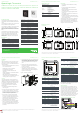
To mount the HVAC thermostat, complete the
following steps:
1. Position the Smart Wall Mounting Plate as
shown in Figure 1.
2. Ensure the Smart Mounting Plates are oriented
to follow the marking that says “This side up”.
Snap them together, ensuring all 4 corner snap
hooks are attached, then attach them to the
junction box using the supplied screws.
3. Use wire nuts to connect the Power/HVAC
and other low voltage signal wiring harness
to the power and heat pump/valve/fan control
signal wires within the electrical box. See
the pre-dened commissioning document for
application-specic wire connections.
4. To connect the unit to the input power and the
relays to the loads, plug the pre-wired power/
HVAC and other signals harness connector into
the female receptacle at the back of the unit
(H1/H2/H3).
5. Hook the tabs at the top rear of the unit housing
into the matching depressions at the top of the
Smart Mounting Plate and rotate the bottom of
the housing toward the wall until it snaps into
place.
6. Secure the housing to the Smart Mounting
Plate with the two small captive screws at the
bottom of the housing.
7. Apply power to the unit by closing the
applicable supply breaker. After connecting
power, OFF mode (factory default setting) will
appear on the LCD display.
Figure 1. Assembly, exploded view
Smart Mounting Plate
4x4 Junction Box
Power/HVAC signal
harness to thermostat
Wiring
H1
H2
H3
5
10
61
ModBus
1
1
12 V
AUX1
AUX2
GND
AI
GND
A
B
ModBus address
S1
OFF ON
1
6
H1 White Connector: 24 VAC Power/HVAC Signals
Pin Name Color Typical Function
1
RH Brown
24 VAC (dedicated to
heating power)
2 RC Violet
24 VAC (dedicated to
cooling/fan power)
3 G3 Grey Fan speed 3 (high)
4 Y Yellow
Cooling output (HVAC),
compressor output (heat
pump) or cold water valve
(FCU)
5 - - Not connected
6 C Black Common
7 W/O/B Blue
Heating output (HVAC),
reversing valve (heat pump)
or hot water valve (FCU)
8 G2/W2 White
Fan speed 2 (medium) /
stage 2 heat (heat pump
with aux. heating)
9 R Red
24 VAC or 24 VDC
(dedicated to product
power)
10 G1 Green Fan speed 1 (low)
H2 White Connector: Low Voltage Signals
Pin Name Color Typical Function
1
AI White
Not connected, reserve for
future use
2 GND Black Ground
3 NC None Not connected
4 AUX2 Yellow
Auxiliary input 2, connects
to Balcony Door/ External
Occupancy sensor with
dry contact output, two
transitions to activate
Pin Name Color Typical Function
5
AUX1 Blue
Auxiliary input 1, connects
to key card/window switch
with dry contact output. Use
normal close/normal open
conguration to activate.
6 12V Red
12 VDC. Connects to
external AUX1 or AUX2
switch/sensor with dry
contact output.
H3 White Connector: Low Voltage Signals
Pin Name Color Typical Function
1
B White RS485 DATA-
2 A Red RS485 DATA+
3 GND Black Ground
S1 Black Switch: Modbus Address Settings*
Pin Signal Typical Function
1
X
1
X
1
=1 if switch is ON, X
1
=0 if switch is OFF
2 X
2
X
2
=1 if switch is ON, X
2
=0 if switch is OFF
3 X
3
X
3
=1 if switch is ON, X
3
=0 if switch is OFF
4 X
4
X
4
=1 if switch is ON, X
4
=0 if switch is OFF
5 X
5
X
5
=1 if switch is ON, X
5
=0 if switch is OFF
6 - Not connected
*Modbus Address= X
1
*2
0
+ X
2
*2
1
+ X
3
*2
2
+ X
4
*2
3
+ X
5
*2
4
Default address is 0. Adjust address range from 1-31 using
S1, enable Modbus and set baud rate in the User Setup
setting (see User Guide for details).
Wiring Diagrams
Note: Prior to beginning an installation, use the
HVAC Wire Harness Templates at the end of this
document to identify the wires/signals coming out
of the 4x4 box and to determine which wires are
connected to which wires on the thermostat. These
templates provide a quick and easy ‘cheat sheet’ to
capture property-specic wiring requirements.
If you have technical questions, please contact the
Schneider Electric Customer Care Center in your
country (see schneider-electric.com/contact).
Generic FCU/Conventional HVAC: 24 VAC
Brown
Violet
Grey
Yellow
Green
Red
White
Black
RH_Heating Power
RC_Cooling/Fan Power
G3_High Fan
Y_Cool Activation
G1_Low Fan
R_Product Power
G2/W2_Medium Fan
W/O/B_Heat Activation
C_Common
GH_HIGH FAN
Y_COOL
GL_LOW FAN
R_24 VAC
GM_MEDIUM FA
N
W1_HEAT1
C_COMMON
Blue
Generic
Heat stages 1 stage
Cool stages 1 stage
Sensing element Digital temperature sensor
Accuracy
±0.5°C@0 to 50°C
(±1°F@32 to 122°F)
Set-point range 5 to 35°C (41 to 95°F)
Display range 0 to 50°C (32 to 122°F)
Display resolution 0.5°C (1°F)
Operating temp. 0 to 50°C (32 to 122°F)
Operating
humidity
0 to 95 % RH (non-condensing)
Storage temp. -20 to 60°C (-4 to 140°F)
Storage humidity 0 to 90 % RH (non-condensing)
PIR detection 120° (±60°)
PIR detection
distance
10m at 0°, 5m at 60°, 5m at -60°
Power
consumption
Standby < 0.5W
Power supply 24 VAC @ 50/60Hz or 24 VDC
Terminal cable
14 AWG to 18 AWG solid or
stranded wire
Load rating 3A resistive, 1A inductive, 1A pilot duty
Protection class IP 30
Housing Flame-retardant PC
Dimensions
120 x 120 x 26.5mm
(4.72 X 4.72 X 1.04 in.)
Pollution degree Pollution Degree 2
Operation type Type 1.B
Control purpose Operating control
Control
construction
Independently mounted control for ush
mounting
Impulse voltage 330V
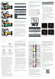
Dimensions mm (in.)
TH907 Series
TH903 Series
Front View Mounting View Back View Side View
26.5
(1.04)
120 (4.72)
120 (4.72)
48 (1.86)
85 (3.31)
120 (4.72)
120 (4.72)
70 (2.72)
60 (2.32)
SpaceLogic Thermostat
TH900 Series for PTAC, Fan Coil, Heat Pump & Gas/Oil Furnace Applications
TH903-P-W, TH903-ZP-W, TH903-ZPM-W, TH907-P-W, TH907-ZP-W, TH907-ZPM-W,
TH907-P-B, TH907-ZP-B, TH907-ZPM-B
26.5
(1.04)
120 (4.72)
120 (4.72)
48 (1.86)
85 (3.31)
120 (4.72)
120 (4.72)
80 (3.15)
70 (2.76)
Front View Mounting View Back View Side View
Precautions
• This product is not intended for life or safety
applications.
• Do not install this product in hazardous or
classied locations.
• Read and understand the instructions before
installing the product.
• Turn off all power supplying equipment before
working on it.
• The installer is responsible for conformance to
all applicable codes.
• External housing may be cleaned with a damp
cloth if it becomes dirty. Do not use any cleaning
agent, especially alcohol.
If this product is used in a manner not specied by
the manufacturer, the protection provided by the
product may be impaired. No responsibility is as-
sumed by the manufacturer for any consequences
arising out of the use of this material.
Regulatory Information
Agency
approvals
FCC CFR 47 Part 15 Subpart B Class B
RSS 247
ICES-003:issue 6
UL 60730-1
UL 60730-2-9
CAN/CSA-E60730-1
CAN/CSA-E60730-2-9
European Conformance CE:
IEC/EN 60730-1
IEC/EN 60730-2-9
RoHS
compliance
2011/65/EU
2015/863/EU
REACH
compliance
1907/2006/EC
Specications (cont.)