
Installation Guide

schneider-electric.com | 2Installation Instructions
© 2020 Schneider Electric. All rights reserved. All trademarks are owned by Schneider Electric Industries SAS or its affiliated companies. January, 2021 tc
Document Number: F-27393-16
Piping
RISK OF EQUIPMENT DAMAGE
•
Do not install in open systems using substantial make-up water.
• Follow proper water treatment practices and system
procedures.
Failure to follow these instructions may cause equipment
damage.
NOTICE
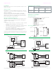
These valves must be piped according to the water flow
diagram below. Two-Way valve flow should go A to AB. Three-
way valves should be applied only as mixing valves (see
diagram).
Best Practice Guidelines
It is recommended to fit a strainer upstream of the valve to
increase reliability and to follow water treatment guidelines as
detailed in VDI 2035.
Recommendations
The pipework system should be flushed prior to the operation.
Installation Notes
• Confirm there is no overhead water source that may drip
onto valve actuator. In normal service, some condensation
may occur on or around the valve. A drip pan may be
necessary or the valve body may be insulated.
• Do not cover the actuator or obstruct the manual operator
lever.
• Reference product label and Product Datasheet
F-27395 (Global) or F-27895 (EU) for additional product
specifications.
It is the responsibility of the installer or product specifier to
verify media compatibility of the valves construction materials
with the supplier of water treatment/heat transfer solution.
Installing the Valve Body
1. Apply PTFE tape to the male pipe thread.
2. Hand screw the pipe into the valve, turning it as far as it will
go.
3. Use a wrench to fully tighten the valve to the pipe. Do not
over tighten or strip the threads.
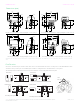
Installing the Actuator on the Valve Body
4.
RISK OF EQUIPMENT DAMAGE
• Do not use the valve body to manually open the actuator.
• Ensure the manual operating lever has clearance to rotate
during operation.
Failure to follow this instruction will result in damage to
the actuator.
NOTICE
Turn the valve stem so the slot on top of the stem is
pointing towards the large keyed post.
5. Do one of the following:
• For a spring return actuator, press the red lever down
and rotate the manual operating lever to align the stem
hole with the valve stem. Then slide the red lever up to
lock the manual lever in place.
• For a non-spring actuator, press and hold the red
release button on the top of the actuator and rotate
the manual operating lever to align the stem hole with
the valve stem, then release the red button.
6. Align the valve body with the actuator so the stem lines up
with the large stem hole and the large keyed post lines up
with the post hole on the bottom of the actuator.
7. Firmly press the valve and actuator together to lock into
place.
The first time the valve is operated electrically, the manual
operating lever of the actuator will move to the automatic
position. The manual operating lever can be used to allow
flushing of the system after installation.
Removing the Actuator
NOTE: Make sure the valve stem rotates freely before and
after installing the actuator. If the stem does not operate freely
it may indicate that the stem was damaged and may require
that the valve be replaced.
1. Press and hold the valve release lever inward, towards the
valve.
2. Lift the actuator from the valve.
3. After the piping is under pressure, check the valve body
and the connections for leaks.
4. After the valve and actuator are installed, power the
actuator and check the operation by varying the control
signal. On spring return models, the valve should return to
its normal position when power is removed.
Theory of Operation
This series of floating valve actuator assemblies is designed
to make incremental adjustments to flow based on the control
signal input. This actuator is not intended for continuous use
in zero dead band control systems. In order to prevent a false
spring return, a solenoid is used to disengage the gear for
spring return. When power is removed for more than two
seconds, spring return valve assemblies return to their normal
position. Non-spring return valve assemblies remain at their
last position when power is removed. The spring return feature
should not be used for routine, normal operation. Spring
Return and Non-Spring Return actuators will automatically
limit the running time of the actuator. The Time-out feature
automatically cuts off the control signal to the valve after three
minutes of continuous operation. Upon change in control
signal direction, the actuator will resume operation.
Note: Do not use the manual operator while power is applied
to the actuator. If the actuator is manually positioned while
power is applied, the calibration cycle must be completed
again for the actuator to function properly. To recalibrate the
actuator, cycle power off for more than 6 seconds.
Maintenance
The ball valve assembly itself requires no maintenance.
The stem and packing design eliminates the need for
packing adjustment for the life of the valve. However, regular
maintenance of the total heating and cooling system is
recommended to provide for sustained optimum performance.