
Installation Guide

schneider-electric.com | 3Installation Instructions
© 2020 Schneider Electric. All rights reserved. All trademarks are owned by Schneider Electric Industries SAS or its affiliated companies. January, 2021 tc
Document Number: F-27393-16
Field Repair
Neither valve nor actuator are field repairable. Replace entire
unit as necessary.
Agency Listings
North America: c-UL-us LISTED per UL 60730-1 & -2-14 and
CSA E60730-1 &-2-14. FCC part15 classB & ICES-003 classB
emissions compliant.
European Union: LVD 2014/35/EU and EMC 2014/30/EU
directives, per EN 60730-1 & -2-14. EN 61000-6-2 immunity
& EN 61000-6-3 emissions compliant. Australia/NewZealand:
Meets requirements to bear RCM mark.
Power/Failure Action (Floating)
Control Signal Position upon power loss
Non-Spring
Return Actuator
Spring Return Open
Actuator - Fail Open
Spring Return
Closed Actuator -
Fail Closed
Power to “Open”
terminal will
open A to AB
Maintain last
position
Will spring A to AB
open
Will spring A to AB
closed
NOTE: Two-Way valve operation described. For a three-way valve, A to AB
operation is the same. B to AB operation is opposite that of A to AB operation.
Wiring and Wiring Diagrams
Make all connections according to job wiring diagrams and in
compliance with local and national electrical codes. Refer to
diagrams for typical wiring.
NOTE:
• Multiple actuators may be connected to a single controller
• Do not exceed the maximum current draw of the
controller.
• Use only one spring return actuator per 10 VA transformer.
• Use of a properly sized, inherently limited, Class 2
transformer is recommended.
• Use only 18…24 AWG (0.75…0.22 mm
2
) copper wire
for all connectors. When using multiple wires under one
terminal do not exceed 2 wires or 20 AWG wire.
Three-Wire Notice: Spring return floating valves feature a two second delay upon power loss to
prevent the loss of valve position during brief power outages. There is a three-second delay at
power-up control signal). For more information see Guidelines for Powering Multiple Actuators
EN-206 (F-26363).
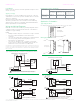
AAB
Supply
Return
Typical Two-Way
Fan Coil Application
Mixing applications
Supply
Bypass
Return
B
AB A
Typical Three-Way
Fan Coil Application
Supply
Bypass
Return
B
AB
A
Three-Way
Constant Flow
Variable Temperature
Application Schematics
Typical applications
For simplicity, balancing valves and control devices are not shown.
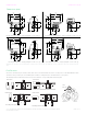
SPDT Floating or (2) SPST Controller
1-Close
2-COM
3-Open
24 Vac Transformer
Line
V
olts
YEL/BLK
BLACK
BLUE
Typical Wiring for M332A0x Non-Spring Return Actuators
24 Vac Transformer
Line
Volts
1-Close
Floating Non-Spring Return Actuator (M332A0x)
Controller
Hot
Common
YEL/BLK
BLACK
BLUE
2-COM
3-Open
1-24 Vac
1
24 Vac Transformer
Line
V
olts
Controller
Hot
Common
Floating Spring Return Actuator (M312A0x or M322A0x)
BLACK
BLUE
YEL/BLK
RED
3-Open
2-COM
4-Close
The 24 Vac/COM supply must be maintained continuously for valve operation.
The valve returns to normal position whenever this supply is interrupted.
1
1
Triac Sink Wiring
24 Vac Transformer
Line
V
olts
1-Close
Floating Non-Spring Return Actuator (M332A0x)
Controller
Hot
Common
1-24 Vac
24 Vac Transformer
Line
V
olts
Controller
Hot
Common
Floating Spring Return Actuator (M312A0x or M322A0x)
RED
BLACK
BLUE
YEL/BLK
YEL/BLK
BLACK
BLUE
3-Open
2-COM
4-Close
3-Open
2-COM
Triac Source Wiring
ac/COM supply must be maintained continuously for valve operation.
The valve returns to normal position whenever this supply is interrupted.
SPDT Floating or (2) SPST Controller
1-24 Vac
2-COM
3-Open
4-Close
V
o
RED
BLK
BLUE
YEL/BLACK
1
Typical Wiring for M312A0x or M322A0x Spring Return Actuators
1
1
The 24 V
24 Vac Transformer
Line
lts