
Installation Guide

schneider-electric.com | 4Installation Instructions
© 2020 Schneider Electric. All rights reserved. All trademarks are owned by Schneider Electric Industries SAS or its affiliated companies. January, 2021 tc
Document Number: F-27393-16
5-1/8
(130)
4-3/8
(111)
1/16 (2)
2-3/8
(60)
3-3/4
(95)
1-3/8
(35)
1-3/8
(35)
2-9/16
(65)
3/4 (19)
2-1/2
(64)
1-11/16
(43)
3/8 (10)
2
(50)
5-1/8
(130)
4-3/8
(111)
2-3/8
(60)
3-3/4
(95)
3/4 (19)
2-9/16
(65)
1-3/8
(35)
1-3/8
(35)
1/16 (2)
1-11/16
(43)
2-1/2
(64)
2-3/16
(56)
5-1/8
(130)
4-3/8
(111)
1/2 (12)
3-9/16
(90)
4-7/8
(124)
3/4 (19)
1-3/8
(35)
1-3/8
(35)
2-9/16
(65)
2
(50)
2-1/2
(64)
1-11/16
(43)
3/8 (10)
5-1/8
(130)
4-3/8
(111)
1/2 (12)
3-1/16
(78)
4-7/8
(124)
2-9/16
(65)
1-3/8
(35)
1-3/8
(35)
1-11/16
(43)
2-1/2
(64)
2-3/16
(56)
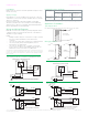
Dimensions (mm)
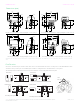
Flow Direction
A notch is cut into the tip of the valve stem. This notch is an external indicator of the closed portion of the ball within the valve.
Check the notch position prior to assembling the actuator to verify the ball is orientated in the correct plane.
The drawings below indicate the stem notch position and the corresponding ball valve flow path.
Two-Way Open
Notched Stem
Ball Position
or
AB
A
A
Two-Way Closed
Notched Stem
Ball Position
or
ABA
Three-Way, A-Port Open, B-Port Closed
Notched Stem
Ball Position
AB
A
B
Three-Way, A-Port Closed, B-Port Open
Notched Stem
Ball Position
AB
A
B
Stem
Indicator
Closed
Open
Two-Way Non-Spring Return. Shipping Weight: 2.07 lbs (940 g) Three-Way Non-Spring Return. Shipping Weight: 2.34 lbs (1060 g)
Two-Way Spring Return. Shipping Weight: 2.25 lbs (1020 g) Three-Way Spring Return. Shipping Weight: 2.51 lbs (1140 g)
All dimensions shown in inches format and are rounded to the nearest 1/16”. An additional 1 inch is required to remove the actuator from the
valve.