Conext™ SW Inverter/Charger Conext SW 2524 120/240 (865-2524) Conext SW 4024 120/240 (865-4024) Conext SW 4048 120/240 (865-4048) Installation Guide 975-0639-01-01 Rev D 7-2015 TM solar.schneider-electric.
Conext SW Inverter/Charger Conext SW 2524 120/240 (865-2524) Conext SW 4024 120/240 (865-4024) Conext SW 4048 120/240 (865-4048) Installation Guide solar.schneider-electric.
Copyright and Contact Copyright © 2013-2015 Schneider Electric. All Rights Reserved. All trademarks are owned by Schneider Electric Industries SAS or its affiliated companies.
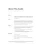
About This Guide Purpose The purpose of this Installation Guide is to provide explanations and procedures for installing the Conext SW Inverter/Charger to a main AC power source such as an AC generator for off-grid application or AC mains (main power grid) for power backup application. Scope The Guide provides safety and installation guidelines as well as information on tools and wiring. Complete balance of system installation is not covered.
About This Guide Abbreviations, Acronyms, and Symbols AC Alternating Current AGS Automatic Generator Start SCP System Control Panel BOS Balance of System SW Sine Wave DC Direct Current VAC Volts, Alternating Current PPE Personal Protective Equipment VDC Volts, Direct Current PV Photovoltaic IP20 Ingress protection rating Reference to see guide (or manual) for more information Ground AC DC LED Light Emitting Diode Denotes a steady LED Denotes a flashing LED Inv Enabled
Important Safety Instructions READ AND SAVE THESE INSTRUCTIONS - DO NOT DISCARD This guide contains important safety instructions for the Conext SW Inverter/ Charger that must be followed during operation and troubleshooting. Read and keep this Installation Guide for future reference. Read these instructions carefully and look at the equipment to become familiar with the device before trying to install, operate, service or maintain it.
Safety Safety Information DANGER ELECTRICAL SHOCK AND FIRE HAZARD Installation must be done by qualified personnel to ensure compliance with all applicable installation and electrical codes and regulations. Instructions for installing the Conext SW are provided here for use by qualified installers only. Failure to follow these instructions will result in death or serious injury.
Safety DANGER ELECTRIC SHOCK HAZARD • For indoor use only. This inverter/charger is designed for off-grid, solar, backup, and hybrid applications. • Do not operate the inverter/charger if it has been damaged in any way. • Do not operate the inverter/charger with damaged or substandard wiring. Wiring must be done by qualified personnel to ensure compliance with all applicable installation codes and regulations. Failure to follow these instructions will result in death or serious injury.
Safety Precautions When Working With Batteries IMPORTANT: Battery work and maintenance must be done by qualified personnel knowledgeable about batteries to ensure compliance with battery handling and maintenance safety precautions. DANGER ELECTRIC SHOCK HAZARD • Determine if the battery is inadvertently earthed (grounded). If inadvertently grounded, remove the source from ground. • Avoid contact with any part of a grounded battery. • Remove ground during installation and maintenance.
Safety WARNING LI LIMITATIONS ON USE Do not use in connection with life support systems or other medical equipment. Failure to follow these instructions can result in death or serious injury. NOTICE RISK OF INVERTER/CHARGER DAMAGE • Never place the Conext SW Inverter/Charger unit directly above batteries; gases from a battery will corrode and damage the inverter/charger. • Never place the Conext SW Inverter/Charger unit in the same compartment as batteries due to an explosive hazard.
Safety FCC Information to the User This equipment has been tested and found to comply with the limits for a Class B digital device, pursuant to part 15 of the FCC Rules. These limits are designed to provide reasonable protection against harmful interference in a residential installation. This equipment generates, uses, and can radiate radio frequency energy and, if not installed and used in accordance with the instructions, may cause harmful interference to radio communications.
Contents Important Safety Instructions Safety Information - - - - - - - - - - - - - - - - - - - - - - - - - - - - - - - - - - - - - - - - - - - - - - - - - - - - - - - - - -vi Precautions When Working With Batteries - - - - - - - - - - - - - - - - - - - - - - - - - - - - - - - - - - - - - - - - viii FCC Information to the User - - - - - - - - - - - - - - - - - - - - - - - - - - - - - - - - - - - - - - - - - - - - - - - - - - - x 1 Installation Materials List - - - - - - - - - - - - - - - - - - - - - - - -
Contents Installation Complete - - - - - - - - - - - - - - - - - - - - - - - - - - - - - - - - - - - - - - - - - - - - - - Multiple Unit Configuration - - - - - - - - - - - - - - - - - - - - - - - - - - - - - - - - - - - - - - - - - - - - - - - - DC Connections for Multiple Unit Configuration - - - - - - - - - - - - - - - - - - - - - - - - - - - - - - - Configuring the System for Multiple Unit Operation - - - - - - - - - - - - - - - - - - - - - - - - - - - - Search Mode Operation in Multiple Unit Configurat
Figures Figure 1-1 Figure 1-2 Figure 1-3 Figure 1-4 Figure 1-5 Figure 1-6 Figure 1-7 Figure 1-8 Figure 1-9 Figure 1-10 Figure 1-11 Figure 1-12 Figure 1-13 Figure 1-14 Figure 1-15 Figure 1-16 Figure 1-17 Figure 1-18 Figure 1-19 Figure 1-20 Figure 1-21 Figure 2-1 Figure 3-1 Figure 3-2 Figure 3-3 Figure 3-4 Figure 3-5 Figure 3-6 Materials List - - - - - - - - - - - - - - - - - - - - - - - - - - - - - - - - - - - - - - - - - - - - - - - - - - - - - - 1–2 Conext SW Front and Side Panels - - - - - - - - - - - -
xiv
Tables Table 1-1 Table 1-2 Table 1-3 Table 1-4 Table 1-5 AC Wire Size In and Out of the Inverter/Charger- - - - - - - - - - - - - - - - - - - - - - - - - - - Recommended Battery Cable Sizes - - - - - - - - - - - - - - - - - - - - - - - - - - - - - - - - - - - Recommended Fuse and Breaker Sizes - - - - - - - - - - - - - - - - - - - - - - - - - - - - - - - - Battery Sizing Example - - - - - - - - - - - - - - - - - - - - - - - - - - - - - - - - - - - - - - - - - - - - Battery Sizing Worksheet - - - - - - - -
xvi
1 Installation The following topics will be covered in this chapter.
Installation Materials List The Conext SW ships with the following items: • One Conext SW unit • One set of owner’s and installation guides • One Battery Temperature Sensor (BTS) • Two Xanbus network terminators • Two sets of 5/16"-8 nuts and washers for the DC terminals, • Two DC terminal covers (red and black) with two sets of #6-32 screws • One Installation bracket with one set of M6 nuts for mounting (not shown) NOTE: If any of the items are missing, contact your dealer and/or sales repre
Materials List Conext SW Front and Side Panels 1 2 TOP TOP 3 7 7 4 6 5 Figure 1-2 Conext SW Front and Side Panels Before you begin to operate the Conext SW after installation, review the front panel features shown in Figure 1-3 and described in the next table. A detailed view of the lights and buttons on the front panel is also shown. Item Description 1 Front Panel contains the Inv Enable and Clear Fault | Reset buttons, as well as various LEDs (status indicator lights).
Installation Item Description 5 AC line terminals. See “AC and DC Terminals, Network and Communication Ports Panel” on page 1–5. 6 Two variable-speed cooling fans maintain a cool internal temperature of critical components. The two fans control airflow through the transformer and power compartments of the unit. Ensure at least 10" (254 mm) of clearance for proper ventilation. 7 Mounting holes for permanent installation. See “Step 2: Mounting the Inverter/Charger” on page 1–19.
Materials List Conext SW AC/DC/Ports Side Panel 3 1 7 b a 4 2 5 6 8 9 Figure 1-4 AC and DC Terminals, Network and Communication Ports Panel Item 1 2 3 4 5 6 7 Description Battery Positive (+) (red) DC terminal connects to the positive bus bar of the DC Switchgear. Battery Negative (–) (black) DC terminal connects to the negative bus bar of the DC Switchgear. XANBUS interface ports are used to connect Xanbus-enabled devices including the optional SCP and AGS. STACKING port.
Installation Conext SW Supplied Accessories 1 2 3 Figure 1-5 Supplied Accessories NOTE: If any of the supplied accessories are missing, contact customer service for replacement. See “Contact Information solar.schneider-electric.com” on page ii. Item Description 1 BTS, the Battery Temperature Sensor consists of: • Connector that plugs into the BTS port on the Conext SW. • Sensor cable is 25 feet (7.6 meters). • Sensor can be mounted on the side of the battery case or on the negative battery terminal.
Materials List Conext SW Required Accessory Figure 1-6 DC Switchgear NOTE: The DC Switchgear is required by electrical code to be installed with the Conext SW inverter/charger in installations within Canada and the USA.
Installation Installation Information Before You Begin the Installation Before beginning your installation: • Read the entire Installation Guide so you can plan the installation from beginning to end. • Assemble all the tools and materials you require for the installation. • Review the Important Safety Instructions on page v. • Be aware of all safety and electrical codes which must be met.
Xanbus Network System Xanbus Network System Xanbus System The Xanbus system includes the Conext SW and other Xanbus-enabled devices. The Conext SW is the device in a Xanbus system that typically provides network power—500 mA at 12 VDC. All of the Xanbus-enabled devices, such as the Conext SW, the SCP, and the AGS are able to communicate their settings and activity to each other.
Installation Xanbus-enabled Products and Other Accessories / 6 9 7 10 4 8 1 11 2 3-ft cable 1 2 3 4 5 6 7 8 9 10 11 Product/Accessory (Shown above) Conext SW DC Switchgear* Conext SW AC Switchgear Stacking Kit (not shown) MPPT 60 150 Solar Charge Controller MPPT 80 600 Solar Charge Controller (not shown) Conext SW On/Off Remote Switch (not shown) System Control Panel (SCP) Conext ComBox Automatic Generator Start (AGS) Conext Battery Monitor Battery Temperature Sensor (BTS) 3-ft network cable (0.
Installation Planning Installation Planning Planning Preparations This section provides information to help plan for a basic installation of the Conext SW. There are two key factors that will have a major impact on system performance. 1. Size and Length of DC Cables To select the appropriate size and length of DC cables, see “DC Cabling” on page 1–14.
Installation AC, DC, and Network Components The illustration below shows the different components that can go into a Conext SW inverter/charger installation.
Installation Planning The illustration below shows which components you may need before you begin your installation. DC Components Xanbus Network Components • 24- or 48-volt battery or batteries, see “DC Component -Batteries” on page 1–14. • System Control Panel (SCP) • Automatic Generator Start (AGS) • DC-rated fuse and/or circuit breaker, see “DC Disconnects and Overcurrent Devices” on page 1–15.
Installation Size of AC Input Wiring Wire size must be coordinated with the overcurrent protection provided ahead of the wire involved, in accordance with the electrical codes or regulations applicable to your installation. Therefore, the wiring used between the main AC source panel’s circuit breaker and the inverter/charger AC INPUT must be sized to match the input breaker rating. Table 1-1 AC Wire Size In and Out of the Inverter/Charger Conext SW Breaker Size Used 30 amps per line Wire Size No.
Installation Planning Table 1-2 Recommended Battery Cable Sizesa Conduitb Cable Length < 5 ft Cable Length 5 to 10 ft Model Maximum Current (A) SW 2524 120/240 120 1 AWG SW 4024 120/240 200 3/0 AWG SW 4048 120/240 120 1 AWG a.From National Electrical Code (NEC) requirements. b.Per NEC Table 310.16 for 177 °F (75 °C) rated copper conductor. IMPORTANT: Using a smaller gauge cable or a longer cable may cause the inverter to shut down under heavy load.
Installation Unpacking and Inspecting the Conext SW Inverter/Charger CAUTION HEAVY LOAD HAZARD Do not lift the unit by yourself. Use two people to lift and mount the unit. Always use proper lifting techniques during installation to prevent injury. Failure the follow these instructions can result in injury. To unpack and inspect: IMPORTANT: Keep the carton and packing material in case you need to return the Conext SW for servicing. 1. Unpack the unit and check the materials list.
Installation Planning Installation Tools and Materials Tools You will need the following tools to install the Conext SW and the battery temperature sensor. ❐ Wire stripper ❐ Crimping tools for fastening lugs and terminals on DC cables ❐ Phillips screwdriver: #2 ❐ Slot screwdriver (1/4" [6mm] wide blade max.
Installation Inverter/Charger Installation Overview This section provides detailed information on installing the Conext SW.
Inverter/Charger Installation Step 1: Choosing a Location for the Inverter/Charger WARNING FIRE HAZARD For indoor use only. Do not install and/or operate in compartments containing flammable materials or in locations that require ignition-protected equipment. Do not cover or obstruct the ventilation openings. Do not install this unit in a compartment with limited airflow. Failure to follow these instructions can result in death or serious injury. \ The inverter should only be installed in a location that
Installation TIP: Align the mounting holes in the center of wall studs. If necessary, fasten a plywood board first to a wall with non-standard-spaced wall studs. Then mount the inverter/charger on the plywood board. 16-inch standardspaced wall studs. (1) Place the installation bracket flat on the wall (or plywood) and mark the positions of the mounting holes on the wall. (2) 5 7/8 in. 149.0 mm (2) Pilot drill the four mounting holes on wall studs (or plywood).
Inverter/Charger Installation Step 3: Connecting the AC Input and AC Output Wires DANGER ELECTRICAL SHOCK AND FIRE HAZARD Make sure wiring being connected to the inverter/charger is disconnected (physically or by opening and locking out the breaker) from all electrical sources before handling. All wiring must be done in accordance with local and national electrical wiring codes. Failure to follow these instructions will result in death or serious injury.
Installation (1) Make the wiring connections to the AC source main panel. (2) Route the AC cable to the inverter/ charger. (3) Remove the wiring compartment cover panel on the inverter/charger. (4) Remove the AC knockouts from the side (3) side AC knockouts or bottom (or both). Do not leave the knockout inside the wiring compartment. (5) Install strain-relief clamps in the AC knockouts. (4) (6) Route the AC input cable through the AC input knockouts and inside the wiring compartment.
Inverter/Charger Installation Step 4: Installing the DC Switchgear and Connecting the DC Cables DC Connection Precautions WARNING BURN AND FIRE HAZARD Connect and disconnect DC wiring only after opening and locking out the disconnect switches or breakers at all AC and DC sources. Failure to follow these instructions can result in death or serious injury. Recommended Cable Sizes and Lengths and Fuse Size For recommended DC cables and fuse sizes, see Table 1-2 and Table 1-3 on page 1–15.
Installation Installing the DC Switchgear next to Conext SW Inverter/Charger T WARNING FIRE HAZARD • Make sure the supplied nuts on the inverter/charger are tightened to a torque of 10–11 ft-lbs (13.5–14.9 Nm). Torque all other connections to the manufacturer’s specifications. • Make sure the bus bar, washer, and nut are assembled in the order shown in Figure 1-12 on page 1–24. Failure to follow these instructions can result in death or serious injury.
Inverter/Charger Installation Connecting the DC Cables to the DC Switchgear WARNING FIRE HAZARD • Use only appropriately sized copper cable. Loose connections, improper connections, and under-rated cables will overheat. • Make sure the supplied nuts on the inverter/charger are tightened to a torque of 10–11 ft-lbs (13.5–14.9 Nm). Torque all other connections to the manufacturer’s specifications.
Installation (1) Route the DC cables from the battery bank to the DC Switchgear. (2) Install a DC fuse (a) on the positive cable near the battery terminal. (3) Open the DC circuit breaker on the DC Switchgear. (4) Connect one connector on the POSITIVE (+) cable to the POSITIVE terminal on the DC Switchgear. The connector goes on first, then the flat washer (steel), then the 3/8” (9.5mm) bolt (brass). (5) Connect the other connector to the POSITIVE (+) terminal on the battery.
Inverter/Charger Installation Step 5: Connecting the BTS and Xanbus-enabled Components WARNING ELECTRICAL SHOCK HAZARD Connect and disconnect DC wiring only after opening and locking out the disconnect switches or breakers at all AC and DC sources. Failure to follow these instructions can result in death or serious injury. Battery Temperature Sensor (BTS) Installing a BTS extends the life of a battery by preventing overcharging in warm temperatures and undercharging in cold temperatures.
Installation WARNING FIRE HAZARD Follow the stacking of wires as shown in 1(a) of the illustration below. Failure to follow these instructions can result in death or serious injury. (1) Install the BTS sensor on the battery. Method (a) involves mounting the sensor to the negative battery post which allows the internal battery temperature to be sensed providing the most accurate results.
Inverter/Charger Installation Step 6: Performing Checks Prior to Initial Start-Up WARNING ELECTRICAL SHOCK HAZARD The Inv Enable button on the Conext SW front panel and the SCP do not disconnect DC or AC input power to the Conext SW. Open and lockout the disconnect switches or breakers at all AC and DC sources. Test with a multimeter before tightening electrical connections. Failure to follow these instructions can result in death or serious injury.
Installation If the test fails at any point, go to “Step 6: Performing Checks Prior to Initial StartUp” on page 1–29 and go through the checklist again to check the installation. Then perform the test again. If the test fails again, see the troubleshooting section in the Conext SW Inverter/Charger Owner’s Guide. Figure 1-15 Conext SW Front Panel Testing in Invert Mode To test the Conext SW in invert mode, using a 100 watt light bulb as the test load: 1.
Inverter/Charger Installation Installation Complete Your installation is now complete. The inverter/charger is ready for use. The preceding tests use a light test load (a light bulb) as a test case. If you encounter problems when using a load over 1000 watts (for example, a hair dryer or microwave), see the troubleshooting information in the Conext SW Inverter/ Charger Owner’s Guide.
Installation Multiple Unit Configuration The Conext SW inverter/chargers support multiple unit configuration to increase power output. This gives the system engineer and/or installer more options to work with when tailoring a system to meet load demands. In a multiple unit configuration, only two Conext SW inverter/chargers of the same model can be used.
Multiple Unit Configuration The Input and Output Neutrals are electrically tied at the inverter terminals. Only a Neutral wire (from the AC Out cable) is necessary from each inverter. AC Out Cable AC Out Cable AC In Cable AC Output Breakers AC In Cable AC Input Breakers AC Bypass breakers are not shown. For detailed wiring illustration, see “DualInverter System Renewable Energy (Solar) Wiring” on page 3–8.
Installation DC Connections for Multiple Unit Configuration Individual overcurrent devices are to be used between the battery positive and each positive cable leading to the DC Switchgear. Keep cable lengths to the two DC switchgears the same in order to balance cable losses. Connect the units as follows: 1. Connect the positive cables. Follow the steps in “Connecting the DC Cables to the DC Switchgear” on page 1–25. Also, do not tie the positives in series together between inverters. 2.
Multiple Unit Configuration Configuring the System for Multiple Unit Operation Verify all DC and AC connections. Check Xanbus network connections and ensure that terminators are installed at devices at each end of the network. The simplest system includes a Xanbus SCP, the two multi-unit-configured Conext SW inverter/chargers, and two Xanbus terminators. For both units to operate in multiple unit configuration, a Master and Slave have to be assigned.
Installation Search Mode Operation in Multiple Unit Configuration Search mode is automatically enabled in multiple unit installations with two paralleled Conext SW units. Only the master Conext SW operates, and the slave unit comes online only when the load exceeds approximately 60% of the rated output of the master unit. When the load drops below 20% of the master’s rated output, the slave unit turns off.
Battery Information Battery Information Battery Bank Sizing Battery capacity Battery size or capacity is just as important as the battery type selected for use with the Conext SW. The batteries are the most important part of your system, so it is recommended that you purchase as much battery capacity as possible. A large battery will extend running time and ensure that your inverter/charger delivers full rated surge.
Installation Estimating Battery Requirements Calculating Battery Size Step 1: Compute Amp-hours For each appliance, compute the number of amp-hours that will be used between charging cycles, as follows: 1. Obtain the wattage. If the wattage is marked on the nameplate rating, use that. Otherwise, multiply the marked voltage and amperage: WATTS = VOLTS × AMPS. 2. Obtain the Watt-hours by multiplying that amount by the hours the appliance will be used: WATT-HOURS = WATTS × HOURS. 3.
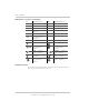
Battery Information Table 1-4 Battery Sizing Example Daily watt-hours needed for this appliance Appliance (A) Power Consumption (Watts) (B) Operating Time per Day (Hours) (= A × B) TV & VCR 200 W 2 hours 400 Wh Small microwave oven 800 W 15 min = 1/4 hour 200 Wh 3 lamps, 60 W each 180 W 4 hours 720 Wh Coffee maker 600 W 15 min = 1/4 hour 150 Wh Hair dryer 1500 W 6 min = 1/10 hour 150 Wh Total daily watt-hours of AC load 1620 Wh × Number of days between charges 3 = Total watt-hour
Installation Restrictions on Motor Size An appliance may require three to six times its normal running current in order to start. The Conext SW can handle surges up to twice its rated amount (surge current) for five seconds. For example, the model Conext SW 4024 120/240 is rated as having a maximum continuous output current of 15 amps and a surge capability of 32 amps. In motors, the locked rotor amp (also called its starting current) may be specified on the motor nameplate as “LRA” or “LRI”.
Battery Information Battery Cabling and Hook-up Configurations Several smaller batteries can be connected to create a battery bank of substantial size. You can connect batteries in three ways: in parallel, series, or series-parallel. To make a larger battery bank, connect individual batteries with heavy cables. The actual size of the cable depends on whether the batteries are connected in parallel or series.
Installation Battery Series Connection When batteries are connected with the positive terminal of one battery to the negative terminal of the next battery, they are connected in series. In a series configuration, the battery bank has the same Ah rating of a single battery, but an overall voltage equal to the sum of the individual batteries. See below.
2 Specifications NOTE: Specifications are subject to change without prior notice.
Specifications Inverter Specifications NOTE: All inverter specifications are at nominal conditions: ambient temperature of 77 °F (25 °C), 24 VDC, unless otherwise specified.
Charger Specifications DC Input SW 2524 120/240 SW 4024 120/240 SW 4048 120/240 No-load power draw (Inverter On) 21 W 26 W 27 W Low battery voltage shutdown cut-off (other values selectable) 21.0 V (default) 21.0 V (default) 42.0 V (default) High battery voltage shutdown 33.0 V cut-off (default) (other values selectable) 33.0 V (default) 62.
Specifications DC Output With a battery temperature sensor (provided) SW 2524 120/240 SW 4024 120/240 SW 4048 120/240 The temperature compensation coefficients on a 24-volt battery are as follows: Flooded: 54 mV × (25 °C – BTS °C) Gel: 54 mV × (25 °C – BTS °C) AGM: 42 mV × (25 °C – BTS °C) The temperature compensation coefficients on a 48-volt battery are as follows: Flooded: 108 mV × (25 °C – BTS °C) Gel: 54 mV × (25 °C – BTS °C) AGM: 42 mV × (25 °C – BTS °C) a.
Physical Specifications Physical Specifications SW 2524 120/240 SW 4024 120/240 SW 4048 120/240 L×W×H 15.2×13.5×7.6 in (387×343×197 mm) 15.2×13.5×7.6 in (387×343×197 mm) 15.2×13.5×7.6 in (387×343×197 mm) Unit Net Weight 50.7 lbs. (23 kg) 67.2 lbs. (30.5 kg) 67.2 lbs. (30.
Specifications Regulatory All Models Safety UL 1741 Ed. 2, UL 1778 Ed. 4 CSA C22.2 NO. 107.1-01, CSA C22.2 NO.
3 Wiring Diagrams “Wiring Diagrams” illustrate the most basic BOS configurations and are for reference only. Specific installations may require additional equipment to meet national or local electric codes. Ensure all safety requirements are strictly followed. For...... See....
Wiring Diagrams 3–2 975-0639-01-01 Rev D This guide for use by qualified personnel only
Single-Inverter System (Off-Grid/Power Backup) Single-Inverter System (Off-Grid/Power Backup) DANGER ELECTRICAL SHOCK AND FIRE HAZARD Installation must be done by qualified personnel to ensure compliance with all applicable installation codes and regulations. Instructions for installing the Conext SW are provided in this installation guide for use by qualified installers only. Accessories Communication Failure to follow these instructions will result in death or serious injury.
ACCESSORIES Communication Cable (Category 5) BTS Communication Cable (6-conductor telephone cable) The actual positions of the Negative shunt and Ground bus may be different than what is shown here. This drawing is for illustration purpose only. 20-contact wiring harness Conext SW Inverter/Charger Conext SW DC Switchgear Xanbus DC Disconnect System Status Battery 20.4 A 53.
Single-Inverter System Renewable Energy (Solar) Single-Inverter System Renewable Energy (Solar) DANGER ELECTRICAL SHOCK AND FIRE HAZARD Installation must be done by qualified personnel to ensure compliance with all applicable installation codes and regulations. Instructions for installing the Conext SW are provided in this installation guide for use by qualified installers only. Failure to follow these instructions will result in death or serious injury.
ACCESSORIES Communication Cable (Category 5) BTS Communication Cable (6-conductor telephone cable) The actual positions of the Negative shunt and Ground bus may be different than what is shown here. This drawing is for illustration purpose only.
Dual-Inverter System Renewable Energy (Solar) Dual-Inverter System Renewable Energy (Solar) Communication Conext SW DC Switchgear Conext SW DC Switchgear Accessories System Control Panel Automatic Generator Start (optional) (optional) Fault/ Warning Power System Status AC Battery 20. 4 A 53.
The actual positions of the Negative shunt and Ground bus may be different than what is shown here. This drawing is for illustration purpose only.
Schneider Electric solar.schneider-electric.com As standards, specifications, and designs change from time to time, please ask for confirmation of the information given in this publication. © 2015 Schneider Electric. All rights reserved.