
Installation Manual


975-0637-01-01 Rev E xiii
This guide for use by qualified personnel only
Figure 1-1 Materials List- - - - - - - - - - - - - - - - - - - - - - - - - - - - - - - - - - - - - - - - - - - - - - - - - - - - - - 1–2
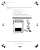
Figure 1-2 Conext SW Front and Side Panels- - - - - - - - - - - - - - - - - - - - - - - - - - - - - - - - - - - - - - - 1–3
Figure 1-3 Front Panel Buttons and Status LEDs - - - - - - - - - - - - - - - - - - - - - - - - - - - - - - - - - - - - 1–4
Figure 1-4 AC and DC Terminals, Network and Communication Ports Panel- - - - - - - - - - - - - - - - - 1–5
Figure 1-5 Supplied Accessories - - - - - - - - - - - - - - - - - - - - - - - - - - - - - - - - - - - - - - - - - - - - - - - 1–6
Figure 1-6 Xanbus System Diagram Example - - - - - - - - - - - - - - - - - - - - - - - - - - - - - - - - - - - - - - 1–8
Figure 1-7 AC, DC, and Network Components - - - - - - - - - - - - - - - - - - - - - - - - - - - - - - - - - - - - - 1–11
Figure 1-8 AC, DC, and Network Components - - - - - - - - - - - - - - - - - - - - - - - - - - - - - - - - - - - - - 1–12
Figure 1-9 Conext SW Mounting Instructions - - - - - - - - - - - - - - - - - - - - - - - - - - - - - - - - - - - - - - 1–19
Figure 1-10 Conext SW AC INPUT and OUTPUT Connections - - - - - - - - - - - - - - - - - - - - - - - - - - 1–21
Figure 1-11 Conext SW DC Connections - - - - - - - - - - - - - - - - - - - - - - - - - - - - - - - - - - - - - - - - - - 1–24
Figure 1-12 Conext SW BTS and Xanbus Connections - - - - - - - - - - - - - - - - - - - - - - - - - - - - - - - - 1–26
Figure 1-13 Conext SW Front Panel- - - - - - - - - - - - - - - - - - - - - - - - - - - - - - - - - - - - - - - - - - - - - - 1–27
Figure 1-14 Multiple Unit Configuration Using Two Conext SW Units - - - - - - - - - - - - - - - - - - - - - - 1–30
Figure 1-15 Connecting Battery Cables- - - - - - - - - - - - - - - - - - - - - - - - - - - - - - - - - - - - - - - - - - - 1–31
Figure 1-16 Multi Menu Screen- - - - - - - - - - - - - - - - - - - - - - - - - - - - - - - - - - - - - - - - - - - - - - - - - 1–32
Figure 1-17 Batteries Connected in Parallel - - - - - - - - - - - - - - - - - - - - - - - - - - - - - - - - - - - - - - - - 1–38
Figure 1-18 Batteries Connected in Series- - - - - - - - - - - - - - - - - - - - - - - - - - - - - - - - - - - - - - - - - 1–39
Figure 1-19 Batteries in Series-Parallel Connections- - - - - - - - - - - - - - - - - - - - - - - - - - - - - - - - - - 1–39
Figure 2-1 Inverter Output Power versus Temperature Derating Graph - - - - - - - - - - - - - - - - - - - - 2–5
Figure 3-1 Single-Inverter System (Off-Grid/Backup) Overview - - - - - - - - - - - - - - - - - - - - - - - - - - 3–3
Figure 3-2 Single-Inverter System (Off-Grid/Backup) Wiring - - - - - - - - - - - - - - - - - - - - - - - - - - - - 3–4
Figure 3-3 Single-Inverter System Renewable Energy (Solar) Overview - - - - - - - - - - - - - - - - - - - - 3–5
Figure 3-4 Single-Inverter System Renewable Energy (Solar) Wiring - - - - - - - - - - - - - - - - - - - - - - 3–6
Figure 3-5 Dual-Inverter System Renewable Energy (Solar) Overview - - - - - - - - - - - - - - - - - - - - - 3–7
Figure 3-6 Dual-Inverter System Renewable Energy (Solar) Wiring - - - - - - - - - - - - - - - - - - - - - - - 3–8
Figures
ConextSWEUROInstallationGuide.book Page xiii Tuesday, July 21, 2015 4:22 PM