
Installation Manual

Multiple Unit Configuration
975-0637-01-01 Rev E 1–31
This guide for use by qualified personnel only
DC Connections for Multiple Unit Configuration
Individual overcurrent devices are to be used between the battery positive and
each inverter. Keep cable lengths to the two inverter/chargers the same in order
to balance cable losses. The battery cable between the two inverter/chargers
should not exceed 30 cm in length.
Connect the units as follows:
1. Connect the positive cables.
Follow the steps in “Connecting the DC Cables to the Inverter/Charger” on
page 1–23.
Also, do not tie the positives in series together between inverters.
2. Connect the negative cables.
Follow the steps in “Connecting the DC Cables to the Inverter/Charger” on
page 1–23.
3. Connect the battery temperature sensors (BTS), if needed.
Follow the steps in “Step 5: Connecting the BTS and Xanbus-enabled
Components” on page 1–25.
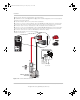
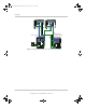
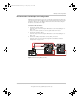
Figure 1-15 Connecting Battery Cables
Battery
Negative
Battery
Positive
Xanbus Stacking REM BTS
Battery
Negative
Battery
Positive
Xanbus Stacking REM BTS
24 V
2
3
1
ConextSWEUROInstallationGuide.book Page 31 Tuesday, July 21, 2015 4:22 PM