
Installation Manual

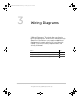


3–4 975-0637-01-01
This guide for use by qualified personnel only
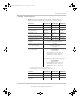
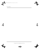
Figure 3-2 Single-Inverter System (Off-Grid/Backup) Wiring
INV IN
BY-
PASS
INV
OUT
Battery
Negative
Battery
Positive
Xanbus Stacking REM BTS
System Control
Panel (optional)
Vented Battery
Enclosure
Battery Temperature Sensor
(BTS)
24-volt Battery Bank Enclosure
Conext SW DC Switchgear
DC Disconnect
N
230 Vac
AC Generator
Conext SW Inverter/Charger
Conext SW AC Switchgear
Negative (–)
Positive (+)
BATTERY
LEGEND
Earth
'&Bus Bar
NOTE: Be sure to check the
generator for a neutral-to-earth
bond and remove it. There can
only be one neutral-to-earth
bond in the system.
System Control Panel
Ente
r
Exit
Fault/Warning
System Status
Battery 20.4 A 53.9V
BatLev E --F
Load 1235W
AC 1 115 W 3202V
Menu
Stand by
12: 00 AM Jan 01
Xanbus
Network
Terminator
Utility
Grid
Earthing
Electrode
Conductor
Main
AC Distribution
Panel
Generator
Disconnect
Earth
Neutral
LINE
LINE
Inverter
AC Distribution Panel
NEUTRAL
Earth
Neutral
LINE
Earth
AC LEGEND
AC Cable
Neutral-to-Earth
Bond inside.
AC Breakers
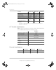
NOTE: If no Grid is available,
the generator can be connected
to the AC breakers in the Conext
SW AC Switchgear, instead of to
a separate AC Generator
Disconnect.
interlock
Automatic Generator
Start (optional)
Xanbus
Network
Terminator
Power
Generator On
Network
Fault
Automatic Generator Start
Conext ComBox
(optional)
Remote Switch
(optional)
This AC Switch is a
customer-supplied
component.
AC
TRANSFER
SWITCH
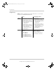
Ensure DC Switchgear
chassis is properly
bonded to Inverter
chassis using supplied
bonding busbar.
The actual positions of the Negative shunt and
Ground bus may be different than what is shown
here. This drawing is for illustration purpose only.
Battery System
Ground
Positive
Battery
Battery
Negative
Communication Cable
(Category 5)
BTS
ACCESSORIES
Communication Cable
(6-conductor telephone cable)
20-contact wiring harness
24-volt or 48-volt
Battery Bank Enclosure
ConextSW_IG_3_Wiring Diagrams_11x16p6.fm Page 4 Friday, January 30, 2015 2:18 PM