
User's Manual

DC in an input transformer should one be
present, which could lead to distortion or a
reduced dynamic range.
A microphone designed for 48 V phantom
powering could draw as much as 10 mA
according to the standard; the SCHOEPS MSTC
64 Ug will draw about 4 mA. This falls well
within the limit set by the prevailing standard.
There are certain commercially available power
supplies, preamplifiers, and mixing desks –
mostly older, but some more recent – which
fail to meet this standard and hence may not
be able to power SCHOEPS microphones ade-
quately.
If in doubt, equipment should be checked to
verify its suitability for professional work with
SCHOEPS microphones. On page 16 a method
is described for checking a phantom supply
quickly and easily.
For P12 the standard allows a current of
15 mA. The SCHOEPS CCM will draw 4 mA.
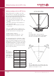
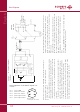
Fig. 2 shows a bal an ced but groun ded am -
pli fier in put. In this case eit her a trans for mer
(see Fig. 1) or ad di tio nal ca pa ci tors ha ve to be
in ser ted into the au dio li ne.
Unbalanced Operation
Our microphones are intended for balanced
operation such as with the VMS 5 U preampli-
fier from SCHOEPS, which is why they should
be operated with balanced inputs. Otherwise
the vulnerability to interference would be
increased. However some equipment only has
unbalanced inputs in which case an unbalanced
input should be balanced with a high-quality
microphone input transformer. This will allow
the signal leads from the microphone to be
kept balanced, for best rejection of interference.
If such an arrangement is not possible, how-
ever, an MSTC 64 microphone may be operated
in unbalanced mode by taking the signal from
pin 2(4) via a coupling condenser with a value
as shown in Fig. 2 above. The signal from pin 3(5)
should be left unconnected; do not short it to
SCHOEPS GmbH · Spitalstr. 20 · D-76227 Karlsruhe (Durlach) · Tel: +49 721 943 20-0 · Fax: +49 721 943 2050
www.schoeps.de · mailbox@schoeps.de
Phantom Powering
14
English
+ phase
- phase
2 (4)
3 (5)
microphone
1
screen
cable
powering
R
S
U
S
input
R
S
P48: U
S
= 48 V ± 4 V; R
S
= 6,8 kW*, I
max.
= 10 mA
P12: U
S
= 12V ± 1V; R
S
= 680 W*, I
max.
= 15 mA
I/2
I/2
I
+ phase
- phase
2 (4)
3 (5)
microphone
1
screen
cable
powering
R
S
U
S
input
R
S
R
R
C
C
* see note in the text concerning tolerances
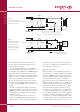
Fig. 3
balanced, ungrounded,
transformerless input.
Condensers must be
inserted into the circuit
and provision made for
polarization resistors.
*
*
*
Fig. 2
input with transformer
(or balanced, ungrounded
transformerless input)
XLR-3
connector
XLR-3
connector
* recommended values:
C: 100
μ
F, 63V; R: 22k
Ω
, 1%
shield
shield
(4)
(5)
(4)
(5)