Instruction Manual Made in USA P: (304) 725-1050 l www.schonstedt.com l info@schonstedt.
Important Notice Schonstedt believes the statements contained herein to be accurate and reliable; however, their accuracy, reliability, or completeness is not guaranteed. Schonstedt's only obligation shall be to repair or replace any instrument proven to be defective within three years of purchase. Schonstedt shall not be responsible for any injury to persons or property, direct or consequential, arising from the use of any instrument. October 2017 – Rev. 1.
Table of Contents Chapter 1: Introduction & Operating Modes 1 Introduction .................................................................................................................... 2 Passive 50/60 Hz ............................................................................................................. 2 Conductive..................................................................................................................... 2 Inductive Clamp ...........................................
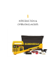
1 INTRODUCTION & OPERATING MODES
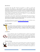
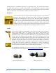
Introduction In general, pipe and cable locators can operate in a variety of modes and frequencies. The following is a brief description of the basic operating modes supported by the Rex Pipe and Cable locator. In addition, the Rex Pipe and Cable locator offers advanced features to suit almost any type of locating challenge, while emphasizing portability, size, and convenience.
transformer box, a telephone switch box, a gas meter, etc.). The clamp then induces a current onto the pipe or cable. In this mode, it is not necessary to provide a return path for the induced current to the transmitter. The induced current will travel on the pipe or cable for a certain distance, making it possible to trace it. Inductive In the inductive mode, the transmitter imposes a signal of the selected frequency onto the pipe or cable to be traced.
Operating Recommendations When using the Rex Pipe and Cable Locator, follow these tips and recommendations to improve and facilitate your locating experience: 1) Whenever possible, use the conductive mode. It provides the strongest and bestcoupled signal. 2) When operating in conductive mode: Try to bury the ground steak on a line perpendicular to the utility to be traced. Verify that a good circuit has been established by: Checking the output current from the transmitter.
2 REX RECEIVER
Automatic and Manual Gain The Rex receiver has the ability to operate in an automatic or manual gain mode. In the automatic gain mode, the sensitivity of the receiver is adjusted automatically, based on the strength of the detected signal, to produce a relatively constant and strong signal strength indication. In the manual gain mode, the user can adjust the sensitivity up or down to suit different locating scenarios. Directional Indication The Rex receiver is equipped with directional indicators (arrows).
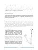
that it produces a “null" (signal strength very close to zero), and then counter-rotate 90 degrees to go back to the original position. To measure depth, simply place the tip of the unit on the ground and press the DEPTH button when the signal strength is at a peak. The achievable depth depends on a number of factors, but typically it is possible to read depth up to 5 to 15 feet (1.5 to 4.2 m).
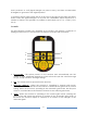
5 DEPTH - When the proper conditions to measure depth are present, pressing this switch will display the target's depth on the LCD (after a delay of 2 seconds). The depth will continue to be displayed on the LCD, along with the word "DEPTH", for as long as the switch is depressed. If the switch is pressed and quickly released, the depth will show on the LCD momentarily. The Rex is factory set to display depth in feet and inches or in meters.
Each time the UP or the DOWN arrow is pressed, the gain is adjusted roughly by 1/30th of the full scale range. Therefore, it takes approximately 3 presses of the UP arrow to add one bar to the graph and approximately 3 presses of the DOWN arrow to delete one bar from the graph. By depressing and holding the UP or DOWN will allow to rapidly scroll the manual gain setting. FREQUENCY/MODE INDICATOR - This LCD area consists of 4 icons: "SONDE", "33 kHz", "82 kHz", and the "Passive Arrow".
ALPHANUMERIC DISPLAY - The alphanumeric display is used to display signal strength and depth. The numeric display is also used for temporary indications of certain operating modes, frequencies, and other brief information messages, as noted throughout this manual. o Signal Strength - This is an indication of the relative signal level detected by the receiver and is a function of the gain setting. Good signal strength will typically be between 200 and 800.
Connectors and Accessories The receiver has a standard 3.5mm headphone jack that accepts any mono or stereo earphones or headphones. Schonstedt also supplies headphones as an optional accessory. The receiver automatically detects the insertion of the headphones or earphones and routes the audio signals to them, silencing the internal speaker. The receiver comes fitted with a rubber plug to protect it from water and dust ingress.
Specifications Operating Frequency: Active: 512 Hz, 33 kHz and 82 kHz Passive: 50 or 60 Hz Sonde: 512 Hz Battery: One 9V Alkaline Battery Battery Life: 12 hours (intermittent use) Audio Output: 10 - 1500 Hz (determined by signal strength) 0 - 70 db SPL (volume controlled) Weight (incl. battery): 2.8 lbs. (1.25 kg) Operating Temperature: -4°F to 140°F (-20°C to 70°C) Water and Dust Resistance Rated IP54, when operated with earphone jack plug (provided) Overall Dimensions: Closed: 17.
Regulatory Compliance and Declaration of Conformity FCC: ++++ This device complies with Part 15 of the FCC Rules. Operation is subject to the following two conditions: (1) this device may not cause harmful interference, and (2) this device must accept any interference received, including interference that may cause undesired operation.
3 REX TRANSMITTER
Automatic and Manual Output Power The Rex transmitter delivers power to the "load" that it is connected to. In the conductive mode, the load is the circuit formed by the cable or pipe being traced, the soil return, and the ground stake. In the inductive clamp and inductive modes, the loads are the clamp and the antenna, respectively. The inductive clamp and inductive modes require the maximum power that the transmitter can deliver.
or AC), an UP ARROW will be shown on the LCD display and the buzzer will be turned on to warn the user of the presence of voltage on the line. The transmitter will continue to retest for the presence of these voltages until they fall below 5 V, in which case it will resume normal signal transmission.
modes, where the output power is internally fixed. Each press increases the output power as follows: P-L (1/2 watt) P-5 (5 watts) >> P-1 (1 watt) >> P-2 (2 watts) >> >> P-L (1/2 watt), and so on. At the 82 kHz operating frequency, only 1/2 watt and 1 watt are available; this is due to FCC regulations. If the transmitter is operating at a higher output power (2 W or 5 W) and the frequency is changed to 82 kHz, the transmitter automatically defaults to P-1 (1 W).
XXX A 3-digit number displayed momentarily on power up indicating the current software version (i.e. 121 = Version 1.21). See section Line Voltage and Impedance Measurement for additional uses of this display area when measuring line voltage and impedance. SMALL 3-DIGIT NUMERIC DISPLAY – This area is used to display the operating frequency (accompanied by the correct units’ indicator, e.g. 82.7 kHz, 512 Hz, etc.).
DC INPUT CONNECTOR - This 5.5 mm/2.1 mm, center positive, DC power connector is used to provide a DC voltage to charge the rechargeable battery. The universal AC/DC power supply provided with the transmitter as a standard accessory plugs into this connector to charge the battery. Alternatively, a DC voltage source capable of supplying 22-30 VDC at 1.5A can be plugged into this connector to charge the battery.
battery indicator will “roll”. As shown below, when the battery is fully charged, it will display “bAt FUL” on the LCD. If the power is OFF, the battery will still charge, but no indication of charging activity or battery status will be shown on the LCD.
Recommendations for Battery Charging and Storage Due to the composition of the battery and the safety features built into the charger, it may be necessary to complete two or more full-charging cycles in order to bring the battery back to full capacity after it has been completely discharged.
To replace the battery, turn the transmitter off, remove the four screws on the front panel’s battery compartment and expose the battery by removing the cover. Gently flip the unit over to let the battery pack drop off into your hand and expose the connector to the main PC board. Reach into the compartment and unplug the connector to disconnect the existing battery (as shown in the below images).
Specifications Operating Frequency: 512 Hz, 33 kHz and 82 kHz Operating Modes: Conductive, all frequencies Inductive, 33 kHz and 82 kHz only Inductive Clamp (optional), 33 kHz and 82 kHz only Max. Output Power: (Conductive mode, @ 1000 Ω load) 512 Hz - 1/2, 1, 2 or 5 W 33 kHz - 1/2, 1, 2 or 5 W 82 kHz - 1/2 or 1 (FCC limited) Max. Output Voltage: 100 V RMS Resistance Meas. Range: 500 Ω to 5 MΩ Voltage Meas.
Regulatory Compliance and Declaration of Conformity FCC: ++++ This device complies with Part 15 of the FCC Rules. Operation is subject to the following two conditions: (1) this device may not cause harmful interference, and (2) this device must accept any interference received, including interference that may cause undesired operation.
4 TECHNICAL SUPPORT/SERVICE INFORMATION
Schonstedt offers technical support and sales support. For any reason regarding usage and application, please contact our technical support team at 888-32-TRACE (888-328-7223). FOR SERVICE OR REPAIR Please ship unit to: Schonstedt Instrument Company 100 Edmond Road Kearneysville, WV 25430 Attn: Customer Service Dept. Return instructions and return form are located online at: https://www.schonstedt.
5 WARRANTY
Schonstedt Instrument Company (Schonstedt) warrants each product of its manufacture to be free from defects in material and workmanship subject to the following terms and conditions. The warranty is effective for 3 years after the shipment by Schonstedt to the original purchaser. Please complete the warranty registration card online at www.schonstedt.com/welcome.