Installation And User Manual SCHOTT Solar Photovoltaic Modules Tips for the installer
PLEASE READ THIS MANUAL CAREFULLY BEFORE INSTALLING OR USING THE MODULES. This manual contains important safety instructions for the PV module that must be followed during the installation and the maintenance of PV modules. Failure to follow these instructions may result in bodily injury or damage to property. Working on a photovoltaic system requires specialized knowledge and should only be attempted by qualified professionals. Introduction Thank you for choosing a SCHOTT POLY™ photovoltaic (PV) module.
Installation And User Manual SCHOTT Solar POLY™ Photovoltaic Modules SCHOTT POLY™ 230, SCHOTT POLY™ 225,SCHOTT POLY™ 220, SCHOTT POLY™ 217, SCHOTT POLY™ 210, SCHOTT POLY™ 202, SCHOTT POLY™ 195 Contents 1. WARNING NOTICES 1.1 General Safety 1.2 Handling Safety 1.3 Installation Safety 1.4 Site Selection 1.5 Tilt Angle Selection 1.6 Mounting Installation 3 4 4 5 5 6 6 2. PV MODULE ELECTRICAL INSTALLATION 2.1 Grounding 2.2 Grounding Methods 8 8 9 3. MAINTENANCE 3.
Danger of Death from Electric Shock The 1. 2. 3. inverter can produce dangerous, high voltage. Be sure to follow all manufacturers’ instructions before installing any PV modules. Use extreme caution when wiring or installing inverter. Be sure to shut down inverter before installing or removing PV modules. Danger of Death from Electric Shock When exposed to light, PV modules produce direct current. When disconnecting any PV modules from a string, a deadly arc can occur. 1.
1.3 Installation Safety 1. Always wear protective head gear, insulating gloves and safety shoes (with rubber soles). 2. Due to the risk of electrical shock, do not perform any work if the terminals of the PV module are wet. 3. Do not install PV modules in the rain, snow or windy conditions 4. Insert interconnect connectors fully and correctly. Check all connections. Cables should be secured to the PV module frames, support structure or raceway to prevent movement. Keep connectors out of direct sunlight.
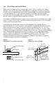
1.6 Mounting and Installation There are several approved ways to mount the SCHOTT POLY™ modules to a support structure. They may be mounted in either portrait or landscape orientation using either the bolt holes provided or using frame clamps (not provided). For all mounting methods a minimum gap of 1/4” (7 mm) between modules is required to allow for thermal expansion. For roof mounted systems a minimum gap of 1” between the module and the roof surface is required to allow for greater ventilation.
Figure 3: Attachment Guidelines – Both Portrait & Landscape Orientations < 54 Ib/Ft2 (< 2600 Pa) 1/2 Use all mounting holes 1/3 Use all mounting holes Use all mounting holes 2/2 2/3 1/8 L Clamping, Long Side (permissible clamp zone) 1/4 L 2/1 2/4 2” Mounting Holes 1/1 1/4 W 3/3 1/4 W 1/4 L 1/4 W Center Support 4/2 4/3 Center Support (portrait only) Center Support (portrait only) 16” 4/1 8” 16” Center Support 1/4 W 8” 3/2 Clamping, Short Side (permissible clamp zone) 1/4 W 2
2 PV MODULE ELECTRICAL INSTALLATION All SCHOTT POLY™ modules are pre-wired with (2) Tyco 4 mm2 PV1-F 90°C UL listed wire and terminated with Tyco Solarlock connectors. This wire intended for interconnection wiring of grounded and ungrounded photovoltaic power systems as described in Section 690.31(A). MINUS is indicated on connector, POSITIVE is not marked. Make sure that all connections are not under load while being connected.
2.2 Grounding Methods 1) Grounding Lug with Thread-Cutting Screw at Grounding Hole 쮿 module frame ~20 in-lbs SS #10 External Serrated Washer (e.g. McMaster 91120A140) Lug 쮿 SS 10-32 X 1/2 Thread-Cutting Screw (e.g. Fastenal 11112837) copper wire #4-6 at 35 in-lbs #8 at 25 in-lbs #10-14 at 20 in-lbs Select a grounding lug listed for direct burial and outdoor use (tin-plated, solid copper lay-in lug with a stainless-steel set screw) capable of accepting a 4-14 AWG copper conductor, e.g.
3) Grounding Lug with Machine Screw at Mounting Hole 쮿 SS 8-32 Nut (e.g. Fastenal 70706) SS #8 Flat Washer (e.g. Fastenal 71008) 쮿 module frame ~20 in-lbs copper wire #4-6 at 35 in-lbs #8 at 25 in-lbs #10-14 at 20 in-lbs Lug SS #8 Flat Washer (e.g. Fastenal 71008) SS 8-32 x 1 Machine Screw (e.g.
3 MAINTENANCE SCHOTT PV modules are designed for long life and require very little maintenance. If the angle of the PV module is 5 degrees or more, normal rainfall is usually sufficient to keep the module glass surface clean under most weather conditions. If dirt build-up becomes excessive, clean the glass surface only with a soft cloth using water. Do not use high pressure spray or chemicals to clean the modules.
No responsibility is taken for the correctness of the information contained herein. SCHOTT Solar assumes no liability in connection with the use thereof. For further information: U.S. Sales and Marketing 2260 Lava Ridge Court, Suite 102 Roseville, CA 95661 Toll free: 888-457-6527 Fax: 916-784-9781 Email: info.solar@us.schottsolar.com www.us.schottsolar.com U.S. Production Facility 5201 Hawking Drive, SE Albuquerque, NM 87106 © 2009 SCHOTT Solar Inc. SCHOTT Solar Inc.