
Datasheet

04-2015, Rev. 0415
www.te.com
© 2015 Tyco Electronics Corporation,
a TE Connectivity Ltd. company
Datasheets and product specification
according to IEC 61810-1 and to be used
only together with the ‘Definitions’ section.
Datasheets and product data is subject to the
terms of the disclaimer and all chapters of
the ‘Definitions’ section, available at
http://relays.te.com/definitions
Datasheets, product data, ‘Definitions’ sec-
tion, application notes and all specifications
are subject to change.
2
SCHRACK
General Purpose Relays
Industrial Relays
Miniature Relay PT
(Continued)
Insulation Data PT2 PT3 PT5
Initial dielectric strength
between open contacts 1200V
rms
1200V
rms
1200V
rms
between contact and coil 2500V
rms
2500V
rms
2500V
rms
between adjacent contacts 2500V
rms
2500V
rms
2000V
rms
Initial surge withstand voltage
between contact and coil 5000V (1.2/50µs)
Clearance/creepage
between contact and coil ≥4/4mm ≥4/4mm ≥4/4mm
between adjacent contacts ≥3.5/9.5mm ≥2.6/3.5mm ≥1.8/3.5mm
Material group of insulation parts IIIa
Other Data
Material compliance: EU RoHS/ELV, China RoHS, REACH, Halogen content
refer to the Product Compliance Support Center at
www.te.com/customersupport/rohssupportcenter
Ambient temperature -40 to +70°C
Cold storage, IEC 60068-2-1 -40°C/16h
Dry heat, IEC 60068-2-2 85°C/16h
Category of environmental protection
IEC 61810 RTII - flux proof
Vibration resistance (functional),
form A (NO)/form B (NC) 7/4g
Shock resistance (functional),
form A (NO)/form B (NC) 20/5g
Terminal type PCB-THT, plug-in
quick-connect
Cover retention, pull/push force 100/100N
Weight 30g
Mounting distance, for mounting on PCB 5mm
Resistance to soldering heat THT
IEC 60068-2-20 270°C/10s
Packaging unit 10/250pcs.
Accessories
For details see datasheet Accessories Miniature Relay PT
Note: indicated contact ratings and electrical endurance data for direct
wiring of relays (according IEC 61810-1); for relays mounted on sockets
deratings may apply.
Product Sets
Complete sets consisting of a relay
mounted on a socket see Package PT
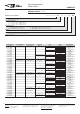
Coil Data (continued)
Coil versions, DC coil, standard
Coil Rated Operate Release Coil Rated coil
code voltage voltage voltage resistance power
VDC VDC VDC Ω±10%
1)2)
mW
006 6 4.5 0.6 48 750
012 12 9.0 1.2 192 750
024 24 18.0 2.4 777 741
048 48 36.0 4.8 3072 750
060 60 45.0 6 4845
1)
743
110 110 82.5 11 16133
2)
750
220 220 165.0 22 64533
2)
750
Coil versions, DC coil with bipolar LED or LED and protection diode
Coil code Rated Operate Release Coil Rated coil
bipol. LED+ voltage voltage voltage resistance +LED pwr.
LED PD
3
) VDC VDC VDC Ω±10%
1)2)
mW
L06 LA6 6 4.5 0.6 48 750+3.5
L12 LB2 12 9.0 1.2 192 750+10
L24 LC4 24 18.0 2.4 777 741+18
L48 LE8 48 36.0 4.8 3072 750+38
L60 LG0 60 45.0 6.0 4845
1)
743+56
M10 MB0 110 82.5 11.0 16133
2)
750+96.5
N20 NC0 220 165.0 22.0 64533
2)
750+202.5
1) Coil resistance ±12%, 2) Coil resistance ±15%,
3) Protection diode PD; standard polarity: +A1/-A2
All figures are given for coil without pre-energization, at ambient temperature +23°C
Coil versions, AC coil, 50/60Hz
Coil code Rated Operate Release Coil Rated coil
STD LED voltage voltage voltage resistance power
50/60Hz 50/60Hz 50/60Hz
VAC VAC VAC Ω±10%
1)2)
VA
506 R06 6 4.8/5.4 1.8 11 1.0/0.85
512 R12 12 9.6/10.8 3.6 48 1.0/0.85
524 R24 24 19.2/21.6 7.2 192 1.0/0.79
548 R48 48 38.4/43.2 14.4 777 1.0/0.87
560 R60 60 48.0/54.0 18.0 1306 1.0/0.87
615 S15 115 92.0/103.5 34.5 4845
1)
1.0/0.86
730 T30 230 184/207 69.0 19465
2)
1.0/0.90
1) Coil resistance ±12%, 2) Coil resistance ±15%
All figures are given for coil without pre-energization, at ambient temperature +23°C