SCHREIBER ENGINEERING 15MED AC/RC – MEDICAL APPLICATION MEDICAL CHILLERS REMOTE PANEL COMMUNICATION INTERFACE FEATURES: • Field removable condensers for remote heat rejection.
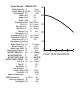
Model Number 15MED-AC/RC Chiller Capacity 15 [Tons] o @ 44 F Water @ 180,000 [BTU/hr] o 95 F Ambient 52.7 [KW] Width 36.25 [in] Height 52.25 [in] Depth 76.00 [in] Volts/Phase 230/3 460/3 [Volts] FLA 78.2. 40.2 [Amps] Min Amps 95 48.8 [Amps] Max Fuse 110 60 [Amps] Charge 20.0 20 [lbs] Refrigerant R-22 Compressor FLA 67.2 34.6 [Amps] Compressor LRA 450 228 [Amps] Compressor HP 2 X 8 [HP] Compressor Type Scroll Water Pump FLA 5.4 2.
WARNING ELECTRICAL HAZARDS 1) TURN OFF MAIN POWER DISCONNECT SWITCH ON THIS MACHINE BEFORE ATTEMPTING TO SERVICE THIS EQUIPMENT 2) THIS MACHINE CAN BE PORTABLE. DISCONNECT ALL POWER SOURCES BEFORE REMOVING CONTROL COVERS. 3) USER IS RESPONSIBLE FOR LOSS OF (OR FAILURE TO USE AND MAINTAIN) ANTI-HAZARD PROTECTIVE COVERS FOR ELECTRICAL EQUIPMENT AS FURNISHED BY THE MANUFACTURER OF THIS MACHINE.
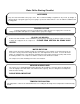
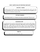
Water Chiller Starting Checklist ANTIFREEZE Keep the water tank filled at the proper level. We recommend adding a maximum of 30 percent, by weight, of ethylene glycol or propylene glycol if you are going to operate the unit below 38o F or in an ambient condition below freezing point. PROPER VOLTAGE A single point power connector is provided at the chiller disconnect to supply power. Check the voltage on the chiller nameplate to see that it matches your power supply.
CONT. WATER CHILLER STARTING CHECKLIST ELECTRIC – POWER A good test to make sure power is off to the unit is to turn on the water pump switch. If power is on, the light on this pump will be on. We recommend you take caution in all judgments about the power being on. The best test to find if the power is on is to use a voltmeter. Please Note: A single – phase condition can cause a pilot light to be out and still have voltage to the unit.
SCHREIBER ENGINEERING START UP SERVICE THE FOLLOWING ITEMS MUST BE COMPLETED PRIOR TO START UP SERVICE BE SURE YOU UNDERSTAND THOROUGH THE CONTENT CONTAIN IN THIS MANUAL; SHOULD YOU HAVE ANY QUESTION REGARD THIS MANUAL FOR INSTALLATION PLEASE CONTACT SCHREIBER ENGINEERING. 9 Appropriate piping has been completed between the chiller and the medical equipment. 9 Correct electrical power has been connected to the chiller. 9 Reservoir and all lines must be full of the proper water / glycol mix.
¥ Make sure you understand thorough the content contained in this manual before installation and operation of the chiller. ¥ Please follow installation instructions recommended in this manual. Failure to follow recommendation will result in void the warranty. ¥ Should you have any question about installation, or any contents in this manual, feel free to contact Schreiber Engineering for consultation. ¥ DO NOT install the chiller in a PIT, inside parking structure, enclosure area.
Chiller Specifications: Refrigeration: The 15MEDGEN2 uses a unique modular refrigeration system. Each refrigeration circuit is mounted on an independent refrigeration “skid” that can be removed from the chiller while the other refrigeration system is still running. This allows for an entire refrigeration system (except the condenser) to be replaced in one piece, while the chiller is still servicing the MR equipment. The chiller includes two (2) independent equal capacity refrigeration systems.
Condenser is designed to operate in a high ambient condition, 120F. This provides the flexibility on the installation location without special requirement. However, proper ventilation is still required. Refrigerant head pressure control is provided by a variable speed drive. It will vary the speed of both fans based on the highest of the two head pressure as measured by the controller. Pumping System The 15MEDGEN2 will have two identical chilled water pumps.
A 50-micron filter and filter housing, 1-1/2” inch fpt connection, will be shipped as loose item. The contractor is responsible to install the filter during chiller installing. All materials are non-ferrous. Construction The chiller is actually three separate sections factory assemble into a single unit. The Reservoir serves as the base, the refrigeration skid and pumps are in the center section, and the condensers serve as the top section.
OVERVIEW The Schreiber Medical Chillers are designed to supply constant chilled water to an MRI system or other scanning system that requires chilled water. These chillers are also designed for Outdoor or Indoor installation. However, if indoor installation is desired, adequate ventilation is required. If necessary, consult with Schreiber Engineering for more information.
PRODUCT FEATURES CONSTRUCTION The chiller is built on a tubular steel base frame; with a 16 gauge powder coated steel cabinet. Components are internally mounted on a 16 gauge galvanized steel base. All of the access panels can be removed without tools. The electrical components are enclosed in a 2 compartment weather proof enclosure. REFRIGERATION SYSTEM The chiller equipped with two 7.5 ton, nominally capacity, compressor/evaporator modules.
overhead pipes and overflowing the reservoir. A water supply and hose should be plumbed to the chiller for filling. Each pump has a shut off valve between the tank and pump suction, and a pressure relief bypass valve, set at 45psig, installed on the discharge and return to manage the flow. There is a common discharge pressure gauge for pumps. A strainer and cleanout valve is installed for refrigeration system. CONTROLS The chiller enclosure is a single enclosure with two compartments.
PLANNING DATA Chiller Installation The chiller and condenser should be installed on a level surface or sub base. Vibration isolation is not provided by Schreiber Engineering and should be installed per requirements of local codes. The bolt pattern diagram contains the corner weights for chiller and condenser mounted together (AC configuration).
NETWORK REQURIMENT: Some chillers may be shipped with optional modem or TCP/IP connection. A phone line and number is required for the modem, and a permanent network connection is required for TCP/IP. Your network’s router will have to be configured so that the IP address for the chiller is exposed outside of the facility’s LAN. Piping Installation: A single chilled water loops is required for the chiller. CHILLER CON. DESIGN FLOW HEAT XCHANGER 1-1/2” FPT 23 usgpm MIN.
START-UP PROCEDURES INSTALLATION INSPECTION: The chilled water supply and return connection are 1-½” NPT. The piping should be copper or PVC and should be insulated. Verify that all connections are made and that all required valves are open. Verify that the main breaker or disconnect is on (disconnect for branch circuit to the chiller, not the chiller disconnect), and check the fuse or breaker size. Compare with the installation requirements.
INITIAL POWER UP: This function and the proceeding function should be performed by an experienced or certified HVAC technician. NOTE: For the visual inspection of the controller feature procedure, it may be more convenient to use the remote terminal. It can be removed from the way bracket and unplugged, and plugged into the chiller with another short length of grounded conductor telephone cable.
FANS: The fans should be spinning CLOCKWISE when looking down on the fan. Air should be drawn from the bottom of the chiller and discharged out through the top. SYSTEM START: Be sure there are no alarm faults present. Sometimes it is necessary to fill the piping system. Therefore, pump can be enabled manually. At the same time, it is recommended that the operation of each pump is verified. NOTE: When two pumps are enabled, disable any one pump will leave other operation.
At the end of the setpoints screen is the compressor rotation screen. Rotation should be enabled. Turn on compressor 1 (pump 1 must still be on) . If the setpoint is below the current tank temperature the compressor will start. The fan will start after a short delay, and will slowly ramp up to speed. Scroll through the current status screens to check return temperature of pump 1., and head pressure of compressor 1.
SPECIFICATION: WEIGHT: 2,250 LBS DRY Reservoir Cap: 70 gallons INPUT POWER: 208/3; 230/3; 440/3; 480/3 FLA: 79-AMPS; 38-AMPS MIN SUPPLY: 95-AMPS; 46-AMPS MAX FUSE: 110-AMPS; 55-AMPS COMPRESSOR LRA: 450 225 PAD SIZE: 84 X 144 INCHES; OPEN HEIGHT CLEARANCE R-22 REFRIGERANT; CHARGE: 20 LBS EACH SYSTEM. Minimum Clearances: Rear: 12 IN (CLEAN OUT) Front : 48 IN (Control Box) Right: 48 IN (AIR INLET SIDE) Left: 48 IN (AIR INLET SIDE) Top: OPEN VENTED Noise: 80-dbA @ 5 FT REV.
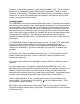
REV. .500 DESCRIPTIONS DATE BY 89.000 22.925 44.151 Chilled Water Return (1-1/2 NPT) 66.120 Chilled Water Supply (1-1/2 NPT) 27.000 29.000 90.000 94.913 27.000 Drain 20.227 27.227 34.427 Fill/Overflow 36.075 3X 7.191 UNLESS OTHERWISE SPECIFIED DIMENSIONS ARE IN INCHES TOLERANCE ARE: FRACTION DECIMALS ANGLES + .XX +.03 +.5 .XXX + .
REV.
REV. DESCRIPTIONS DATE BY 92.336 88.302 2X 16.500 2X 36.000 2X 16.500 2X 1.500 8.068 1ST FAN MOTOR ACCESS PANEL 2ND FAN MOTOR CONDENSER COIL ACCESS PANEL 36.340 VFD ENCLOSURE 52.824 46.744 26.050 24.488 17.573 46.074 2" X 2" X 36" ANGLE IRON 46.074 UNLESS OTHERWISE SPECIFIED DIMENSIONS ARE IN INCHES TOLERANCE ARE: FRACTION DECIMALS ANGLES + .XX +.03 +.5 .XXX + .
REV. DESCRIPTIONS DATE BY 6.721 2X 2.000 2X 10.000 36.340 35.135 2X 10.000 2X 10.000 1.205 WATER RETURN CONNECTION (1-1/2" NPT) 13.388 2X 6.500 26.476 2X 22.579 FILL PORT (1" NPT) 1/2" WATER RETURN CONNECTION (** NOT USED **) 2X 11.000 2X 31.476 2X 2.000 88.302 90.000 PRESSURE GAUGES 6.721 OVER FLOW (1" NPT) WATER LEVEL VIEW PORT 27.435 29.935 34.476 2X 17.476 5.385 4.935 27.000 WATER DISCHARGE CONNECTION (1-1/2" NPT) 1/2" WATER DISCHARGE CONNECTION (** NOT USED **) 29.000 27.
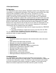
ft 200 160 6.125 45 48 50 120 52 51 51 53 50 48 80 4.0625 40 0 N P S H r 20 10 0 4 h p 2 US gpm 10 20 30 40 Curve No.: GP NPE/NPE-F Schreiber Engineering 1ST-2HP 08/14/05 .ufs GOULDS Catalog: GLPUMPS, vers 2 CC_ENDSUCT_C - 3600 Size: 1ST Speed: 3500 rpm Curve: 6.
Reservoir Drain 4 3 REV TITLE DESCRIPTION 2 REVISIONS DATE REVISED 1 APPROVED A B C D 1⁄2" Shutoff valve provided inside chiller 8 7 NOTES: Pressurized water line with shutoff valve must be provided at the chiller site. The chilled water reservoir is filled directly through the fill port, and not through the supply or return lines. A pressurized water supply with a shutoff valve and hose are all that is required. 6 Tank Fill 5 4 3 PHILIPS INTERCONNECT 2 PHILIPS PIPING INTERCONNECT.
A B C D E F G H 8 2 7 7 2 Hot Gas Connections 1 6 2 6 2 Hot Gas Connections 1 5 Chiller End View All connections are 1⁄2" Liquid Connections 1 4 4 Schrader Valves (field installed) Liquid Lines- 5/8" 25' or more of rise requires a trap at the base and one along the mid point of the rise (Ex.
DRAIN ½" FPT SIGHT GLASS FILL/OVERFLOW 1" Npt PUMP #1 Back Up Pump EVAPORATOR #2 AND ISOLATION VALVE EVAPORATOR #1 AND ISOLATION VALVE STRAINER Manual Flow adjustment Valve Position ¾ close FLOW SWITCH Check valve 1 Check valve 1 CHILLER INTERNAL City Water/Alternate Supply CWR Field Install press. gauge Field Install press.
CRANKCASE HEATER#2 CRANKCASE HEATER#1 C:/MYDOC/SCHREIBER/ELECTRICAL/1055/ 1055_REVB L1 L3 L2 L1 VFD T3 T2 T1 T3 T2 T1 T3 T2 T1 T3 T2 T1 FM LLWRSCFRLPHPBF J1 J9 FUSE 5X20 J10 Rx-/Tx- J2 J11 Fan Motor Contactor Low Level Float Switch Water Pump Contactor Refrigerant Solenoid Compressor Contactor Fan Relay Low Refrigerant Pressure Switch High Refrigerant Pressure Switch BACK FLOW SOLENOID VALVE T3 T2 T1 T3 W T1 T2 2FM 1FM PRESSURE TRANSDUCER 2 PRESSURE TRANSDUCER 1 V U
C:/MYDOC/SCHREIBER/ELECTRICAL/1055/ 1055_REVC - added phasemonitor B3 - DISCHARGE TEMPEARTURE B4 - RETURN TEMPERATURE - 1HP B5 - RETURN TEMPERAURE - PROCON CRANKCASE HEATER#2 CRANKCASE HEATER#1 FUSES LINE REACTOR 2C 1C 1W 1W PUMP#2 PUMP#1 VFD L1 U L2 V L3 W COMPRESSOR#2 T1 T2 T3 T1 T2 T3 COMPRESSOR#1 T1 T2 T3 T1 T2 T3 T1 T2 T3 PRESSURE TRANSDUCER 2 PRESSURE TRANSDUCER 1 FM LLWRSCFRLPHPBF 2FM FUSE 5X20 J10 Rx-/Tx- J2 J11 J3 J12 B J5 J14 J15 TO FW ON VFD TO 12V ON VFD COM RE
CRANKCASE HEATER#2 CRANKCASE HEATER#1 T1 T2 T3 T3 T1 T2 T2 T3 T1 B3 - DISCHARGE TEMPEARTURE B4 - RETURN TEMPERATURE - 1HP B5 - AMBIENT TEMPERATURE PROBE FUSES 2C T3 LLWRSCFRLPHPLA- PRESSURE TRANSDUCER 2 PRESSURE TRANSDUCER 1 J1 J9 J2 J11 REQUIRE FIELD CONNECTION FUSE 5X20 J10 Low Level Float Switch Water Pump Contactor Refrigerant Solenoid Compressor Contactor Fan Relay Low Refrigerant Pressure Switch High Refrigerant Pressure Switch Low Ambient Fan Control NO7 T1 T2 C7 1C J14 T3
CHILLED WATER DISTRIBUTION PIPING The chilled water distribution piping is an important factor in the performance of the water chiller. Proper piping will prolong the LIFE of your chiller. This chiller is designed to be a containment free system. The chilled water piping should be the same. NO BLACK IRON PIPE. 1. If you are installing this water chiller to some existing chiller water lines (Black of galvanized) there is a good chance there will be rust in this system.
INSTALLATION INSTRUCTIONS Air of Water Cooled Chillers 1. When the chiller is delivered, check for any shipping damage. If any are found, a freight claim should be filed at once with the carrier. 2. This water chiller is designed with a contaminant free chilled water system, stainless steel reservoir, and all copper evaporator ion brazed plate evaporator. Installed properly, it will give you years of trouble free service.
SPECIAL INSTRUCTIONS ELECTRICAL CONTROLS- Control Circuit 24 Volts The high-pressure switch will shut off the refrigeration system in the event the pressure is too high. High pressure can be caused by the condenser becoming restricted, by foreign material on the outside surface of the condenser, or if the fan motor is not running. If the high-pressure limit switch should cut out, there is a manual reset switch, which is located at the control panel on the right side.
OPERATION OVERVIEW OF OPERATING SEQUENCE: The 15MEDGEN2 chiller is a 15 ton air cooled chiller designed specifically for the Medical Cooling application. The chiller consists of dual equal circuit refrigeration system, large chilled water reservoir, dual redundant chilled water pumps, variable speed condenser fans, and an advanced microprocessor controller. During normal operation, one pump will run continuously.
CHILLER SYSTEMS: CHILLED WATER CIRCUIT All of the bypassed water returns to the reservoir through the evaporators. The return line water is diverted to both evaporators. The pump motor is INTERNALLY overload protected. In the case of an overload the pump will shut off. The controller will show a “CIRCUIT #1 Flow” error. When the alarm is reset, the pump will restart if the motor has cooled down to the point where the overload is closed.
to allow for flow disruptions caused by a changed in valve position or bubbles in the system. Backflow Kit Since the chilled water reservoir is vented to the atmosphere, water in pipes above the water level of the reservoir will flow back and overflow the reservoir when the pumps are shut off. To prevent this, a backflow kit consisting of a solenoid valve on the return line on chilled water return, and a check valve on the pump discharge is provided.
COMPRESSOR/EVAPORATOR SYSTEM Refer to the illustration on the next page for detail below: Each refrigeration system is mounted on a galvanized steel skid, and is completely self contained. It contains the following: High Pressure Switch The high pressure switch is a manually resetting, totally encapsulated switch that is mounted on a Schrader valve connection. If the switch requires replacement it can be unscrewed from the piping system without loss of refrigerant.
The sight glass moisture indicator is provided for charging purposes and to detect the presence of water in the refrigeration system. Thermostatic Expansion Valve (TEV) The TEV meters liquid refrigerant into the evaporator. It has a factory set superheat of 10 F and should not require adjustment. It is an externally equalized valve. In no circumstances should the equalizer tube me remove or plugged.
If the speed calculated by the controller is lower than the minimum frequency allowed, the fans will completely turn off. The parameters in the variable speed drive itself are factory set and should not have to be changed for any reason.
Controller Quick Reference Guide: This section describes some of the common functions performed in the controller. Basic Navigation MAIN MENU Use the UP and DOWN arrow keys to scroll through the available menus. The currently selected menu will appear in all capital letters with an arrow next to it. Press the ENTER key to go into that menu. INSIDE A MENU LOOP Use the UP and DOWN arrow keys to scroll through the screens in a menu. When at a screen, the cursor is in the upper left hand corner.
Basic Tasks Enabling/Disabling pumps and compressors: At the chiller: 1. 2. 3. 4. Press the PRG key Scroll down to the CURRENT STATUS Screen and press enter. The screen will change to the RUNNING STATUS screen. Press the UP arrow key once to go to the SYSTEM ON/OFF screen. 5. Press the ENTER key to move the cursor to the different devices. Use the UP or DOWN arrow keys to turn each device off or on. At the terminal 1. Press the ON/OFF key. 2.
Checking Alarm History At the chiller 1. 2. 3. 4. Press the PRG key. Scroll down to the ALARM HISTORY menu and press ENTER. Use the UP arrow to review past alarms. To clear the alarm history, press the UP and DOWN arrow keys simultaneously for 5 seconds.
Controller Operation The 1055 can be controlled from 2 locations; the built-in display on the controller (located inside the main chiller enclosure) and from the remote mounted terminal. All control functions can be performed at both locations; however, there are more buttons on the remote terminal that allows faster access to various menu functions.
Chiller menu descriptions Key name in parentheses denotes the shortcut key for accessing that screen directly. MAIN MENU (MENU or PROG) CURRENT STATUS (BLUE key) RUNNING STATUS Shows the current on or off status of the system pumps and compressors. LOOP STATUS Displays the current discharge temperature and return temperature for each pump loop. COMPRESSOR STATUS Displays the head pressure and suction pressure for each refrigeration circuit. Suction pressure display is optional.
Sets and displays the main temperature setpoints. DISCHARGE SETPOINT DISCHARGE: The setpoint for the chilled water reservoir. This temperature will be delivered through both pump loops. HIST: This is the differential around the setpoint of which the system will cycle. HIST = Histeresis. A 50 F setpoint with a 1.0F differential means the system will turn on at 51 F and shut off at 49 F.
automatically choose the correct rotation sequence, either forward or reverse. RUN HOURS (MAINTENCE key) Displays the run hours for each compressor, pump and fan. FACTORY SETTINGS- Password Protected These parameters are discussed in the special maintenance section of the manual. ALARM HISTORY Displays the last 25 alarms. Use the UP key to scroll through each alarm. Every alarm is time and date stamped. Pressing the UP and DOWN arrows simultaneously will reset the alarm history.
DELAY: A filter on the input to prevent nuisance trips. MANUAL CONTROL (INPUT/OUTPUT key, password protected) Allows the inputs and outputs to be bypassed around the control system and manually set to specific values. This is used for service and test purposes only. The special maintenance section describes the functions of manual control.
8 7 6 5 4 3 2 1 24VAC Red 24VAC Black Fan Relay J9 J11 J12 NC8 C7 J14 C8 NO8 C7 J13 NO7 NO6 C4 C4 NO5 NO4 C1 N03 C1 N01 NO2 Rx+/Tx+ GND Rx-/Tx- Controller H H J15 J10 14 c 11 7 G FUSE 5X20 J3 J4 J5 ID1 ID2 ID3 ID4 ID5 ID6 ID7 ID8 IDC1 G FR1 J2 VG VG0 Y1 Y2 Y3 Y4 J1 B4 BC4 B5 BC5 1 B1 B2 B3 GND +VDC G G0 2 Circular Connectors F F Aux Wire Pass Through CC1 CC2 Backflow Kit Terminal Block E c E BFTB Transformer D D Disconnect Wire Duct A1 C
5 4 REV VFD Detail 3 TITLE DESCRIPTION 2 REVISIONS DATE REVISED 1 4/8/2003 APPROVED H A B C D E 4 3 T3 L3 2 1055_TERMINAL_WIRING.
Non Fused GCHE Pump C1 Compressor 1 P2 4 4 C2 Compressor 2 Crankcase Heater 3 3 REV TITLE VFD REVISIONS Fan Motors 5A DESCRIPTION 2 DATE REVISED 1 4/8/2003 APPROVED D E F G H A 7 6 5 Cryo Cooler Pump 2 1055_TERMINAL_WIRING.
A B C D E F 8 B1 7 Circuit1 Pressure CC2-7 B2 B3 Circuit2 Pressure CC2-7 GND 6 Discharge Temp CC2-7 CC2-7 ANALOG INPUTS VDC 6 5 BC5 B5 BC4 5 Return Temp Pump 1 Return Temp Pump 2 B4 G 7 4 From 24VAC Black 4 REV ANALOG INPUTS 3 3 VG0 H 8 Y1 VG REVISIONS 2 DATE REVISED 1 JEFF JOHNSON DRAWN BY 1 DATE APPROVED 4/8/2003 4/4/2003 Analog Input/Output Wiring 1055_TERMINAL_WIRING 1055_TERMINAL_WIRING.
Controller NO1 11 F1 14 CC1-11 A1 2 P1 CC1-14 4 3 REV TITLE DESCRIPTION 2 REVISIONS DATE REVISED 1 APPROVED A B C D E F 8 C4 C2 C1 VFD-12V NO8 NO5 NO4 NO3 NO2 7 6 CC2-7 A1 A1 A1 A2 A2 A2 5 VFD-FWD F1 7 LL2 C2 BF2 P2 LL1 C1 BF1 A2 CC2-14 4 VFD Start Signal ALARM Lamp Fan Relay Liquid Line Solenoid Compressor 2 Pilot Lamp Backflow Kit Valve Cryo Compressor Pump Pilot Lamp Liquid Line Solenoid Compressor 1 Pilot Lamp Backflow Kit Valve GCHE Pu
A B C D E F G H 8 8 7 24VAC Red c CC2-7 CC2-2 CC1-7 CC1-2 24VAC Black 6 6 REMOTE ON/OFF (OPTIONAL) FIELD INSTALLED Float FS2 FS1 LP2 HP2 LP1 HP1 G0 G 5 CC2-3 CC2-1 CC1-3 CC1-1 5 4 4 ID3 7 3 REV 3 IDC1 ID8 ID7 ID6 ID5 ID4 ID2 ID1 TITLE REVISIONS 2 DATE REVISED 1 JEFF JOHNSON DRAWN BY 1 DATE APPROVED 4/8/2003 4/4/2003 DIGITAL INPUT WIRING 1055_TERMINAL_WIRING 1055_TERMINAL_WIRING.
Maintenance This section describes routine maintenance functions that need to be performed periodically. Chilled Water System Glycol Solution Concentration and Level • A warning alarm will be generated when the reservoir level becomes too low. Filling with water will clear the alarm. By reviewing the alarm history, the rate of water loss can be determined by checking the time between subsequent water level alarms. The water level should be inspected by a time in between those alarms.
SERVICE NOTE: This section is for qualified service personnel only. Procedures outlined in this section of the manual can cause personal injury or permanent damage to the chiller and the equipment it is cooling. If you have any questions about the procedures outlined in this section please contact Schreiber Engineering directly. Refrigeration System The Chiller is made up of two separate refrigeration system, the only shared components is the condenser and it’s fans.
3. Stop the compressor when the suction pressure is just above vacuum. 4. Disable the compressor. Compressor Removal 1. 2. 3. 4. 5. 6. Pump down system to be replaced. Close suction and discharge valves. Evacuate remaining refrigerant out of the compressor. Shut down compressor system. Turn off main disconnect. Remove crankcase heater leads, and compressor power leads from the contactor. Record color sequence of leads. 7. Turn on disconnect. 8. Remove leads from the compressor motor adapter. 9.
fan speed. The band is the value around the setpoint of which controls the speed signal. If the head pressure is below the setpoint by the value of the band or more, the controller sends the minimum output of 0 volts DC. If the head pressure is greater than the setpoint by the value of the band or more, the controller sends the max output; 10 VDC. If the head pressure falls between the setpoint value plus or minus the band, the speed is adjusted accordingly.
The range around the setpoint in which the fans run at partial speed. Above the band the fans are full speed, below the band the fans are off. Condenser Fans Service Procedures Transducer Replacement 1. 2. 3. 4. 5. Disable Variable Speed operation Unplug the signal cable from the faulty sensor, Unscrew the sensor. Replace with new sensor and reconnect cable. Enable Variable Speed operation VFD Bypassing.
WARNING Overcharging a refrigeration of air conditioning system can be dangerous **** If a refrigeration system is overcharged and that it is sufficient to immerse the major parts of the motor and compressor in liquid refrigerant, a situation has been created which, when followed by unusual circumstances can lead to compressor housing seam separation or rupture.
Ignition cannot occur at the venting terminal without the presence of contaminant air, and cannot occur externally from the venting terminal without the presence of an external ignition source. It is, therefore, essential that any air in a refrigeration, air conditioning, or heat pump system be completely removed when the system is manufactured – when the system is installed – and whenever the system is field processed a result of field service.
5. With a Megger, Hi-Potential Ground Tester, or other suitable instruments which puts out a voltage between 300 and 1500 volts, check for a ground separately between each of the three C, S, & R leads and ground (such as an unpaired tube on the compressor). Do not use a low voltage output instrument such as a volt-ohmmeter or other such continuity instruments, as these will not detect a low level fault (ground). 6.
Servicing refrigeration and air conditioning systems can be dangerous, and the personnel servicing such equipment should exercise extreme caution in all respects. The precautions discussed in this bulletin deal only with those dangers associated with VENTING TERMINALS. CRANK CASE HEATERS This unit has a CRANK CASE HEATER on the compressor. It is important to the life of this compressor that you follow the instructions.
Factory default setting For PCO2 Controller: (1055AC/WC and 15MED) Under Main Menu CURRENT STATUS CURRENT ALARMS USER SETTINGS RUN HOURS FACTORY SETTINGS ALARM HISTORY DATE AND TIME SENSOR CALIBRATION DIG-IN CALIBRATION MANUAL CONTROL CURRENT STATUS – THESE ARE ONLY INFORMATION SCREENS – NOTHING CAN BE CHANGE Running Status Pumps: 1 2 yes Comps: 2 no TCON TCOFF System Status Discharge: Discharge temperature reading Return #1: Return #1 temperature reading Return #2: Return #2 temperature reading Circuit #1
Setpoints – The customer can change this setting based on their requirement. Temp Rise: 10.0 0F Hist: 01.0 0F High Temp Alarm – The customer can change this setting based on their requirement. Set: 85.0 0F Hist: 05.
Minimum Off: 010 s Fan Control – Head Pressure Control Setp: 190 Band: 030 Vspeed: ENABLE / DISABLE Min Freq: 030 Max: 060 Condenser Fan Config VFD minimum: 000 Hz VFD Maximum: 065 Hz Factory Settings Temperature Unit: 0F Pressure Units: PSI Changing this parameter will not display correct reading in BAR Password Maintenance Factory Pass: 0177 Supervisor setup Ident: 001 Baud: 1200 Protocol: n/a Unit Configuration Evap Sensors: No Voltage Monitor: Yes Misc Settings Tiem Betw Comps: 010 s Screen Saver Delay:
Current: Discharge temperature current reading Offset: 00.0 Offset value Return Temp #1 Current: Discharge temperature current reading Offset: 00.0 Offset value Return Temp #2 Current: Discharge temperature current reading Offset: 00.
Float switch Enabled: Yes Current: Closed Delay Alarm if: Open 01 s Remote ON/OFF Enabled: Yes Current Closed Delay Alarm if: Open 01s MANUAL CONTROL PASSWORD PROTECTED 0177 Digital input #1 Control State: AUTO / MANUAL Input State: Closed / OPEN HP switch #1 Digital input #2 Control State: AUTO / MANUAL Input State: Closed / OPEN LP switch #1 Digital input #3 Control State: AUTO / MANUAL Input State: Closed / OPEN HP switch #2 Digital input #4 Control State: AUTO / MANUAL Input State: Closed / OPEN LP swit
Digital Output #2 Control State: AUTO /MANUAL Input State: Closed / OPEN Compressor #1 Status Digital Output #3 Control State: AUTO / MANUAL Input State: Closed / OPEN Pump #2 Status Digital output #4 Control State: AUTO / MANUAL Input State: Closed / OPEN Compressor #2 Status Digital Output #5 Control State: AUTO / MANUAL Input State: Closed / OPEN Condenser Fan Status Digital output #6 Control State: AUTO / MANUAL Input State: Open / CLOSED AUX_OUT Digital output #7 Control State: AUTO / MANUAL Input Stat
Input State: :0000 – manually input values Return Temperature 2 Analog Output #1 Control State : AUTO / MANUAL Input State: :0000 – manually input values Condenser Fan Speed Analog Output #2 Control State : AUTO / MANUAL Input State: :0000 – manually input values Damper opening This controller has two-stage compressor settings, the discharge temperature for stage 1 and temp rise for stage 2. These setting are located in USER SETTINGS screen. Stages cycle ON/OFF is based on these settings.
Setting point: In this example, we ignore HIST. setting Discharge: 47 0F Temp rise: 10 0F Water temperature reading: Discharge: Return #1: 60 0F 63 0F Again, stage 1 is activated since discharge temperature reading is above discharge temperature setting. This time stage 2 is also activated. The discharge temperature reading is 60 0F, which is above the sum of the discharge setting and temp rise setting (47+10 = 57).
TROUBLE SHOOTING ALARM CONDITIONS Low Pressure Circ. #1 or #2 High Pressure Circ. #1 or #2 POSSIBLE CAUSES CHECKS & REPAIR Low in Gas due to leak *Check for leak & Repair Liquid line sol. Valve not energizing. *Verify valve is good by applying 24 vac directly. Inadequate return water. *Check and clean strainer. Ambient Temperature *If ambient temp below 20°F additional gas is needed. Bad Fan Motors *Manually turn on fan and check current. Restricted flow through condenser.
Lose of Water Circ. #1 or #2 Bad pump *Measure amp draw U physically check pump condition. Bad Flow Switch *Measure terminal ID5/ID6 and IDC1 if voltage below is 20 vac it is bad. Restricted Water Return *Water not allowed to return to chiller.
CHILLER PARTS IDENTIFICATION