Instruction Manual S1580ISS1
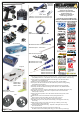
Additional Items Required Soldering Iron CR266 40w CR275 80w Transmitter and Receiver U3107 - Solder AM701011 - Low Profile 4mm Connector 24K - pk2 AM701012 - Low Profile 5mm Connector 24K - pk2 Schumacher Racing stocks and distributes the following manufacturers products and full product listings are available on our website at www.racing-cars.com PLEASE NOTE THAT SOME OF THE PRODUCT RANGES BELOW ARE ONLY AVAILABLE IN THE UNITED KINGDOM. E.S.
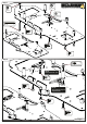
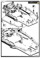
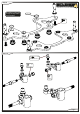
Step 1 x1 Alloy M3 Nyloc x1 Alloy M3 Nut x1 M3 Washer M3 x 25 x1 x2 M3 x 8 x1 M3 x 10 x4 M3 x 6 Step 2 x1 Low Ball Ultra Short NOTE Leave loose for now. x1 M2.5 x 8 x2 M3 x 8 NOTE This position may be adjusted later.
Step 3 x4 x3 M3 x 6 Low Ball Ultra Short x2 M3 x 12 M3 x 4 x1 x3 M3 Washer Use the M3x12 Cap head screw and washers to fit the inserts. Tighten the screw until the M3 thread insert is pulled into the carbon fibre part as shown. CR520 CR520 x2 M3 x 6 x2 x4 M3 x 8 Step 4 M3 Thread Insert x1 M3 x 6 Patched x2 M3 x 6 x1 Ball Stud Short 1.
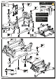
Step 5 A NOTE Adjust all five M2.5x8 button head screws to give minimal clearance but free rotation. Do not overtighten. x4 Step 5 B 1.50mm M2.
Step 6 A x6 M3 Thread Insert x2 Low Ball Ultra Short x4 x2 M3 x 6 Patched M3 x 6 Step 6 B x2 M3 x 8 Page 5
Step 7 x4 M3 x 6 x2 M3 x 6 Page 6
Step 8 A SILI C OIL ONE 120 00 E CON SILI 0000 3 OIL x3 M3 x 14 Use the included spanner to tighten the sockets. Make two side dampers the same with the short sockets. Step 8 B Page 7 Make the centre damper with the long sockets.
Step 9 Be careful to ensure the o’rings are fully seated and concentric. O`ring x 4 x2 M3 x 6 Step 10 x2 Low Ball Ultra Short x4 Black 0.
Step 11 x2 M3 x 6 Use these shims to adjust the droop. We recommend fitting three shims. Step 12 A Use these shims to adjust the ride height and caster. See Step 12B for more information. x4 Grey 0.5 mm x4 Grey 1.0 mm Spacer B Spacer A x2 M3 x 6 x2 x2 M3 x 8 Page 9 M3 x 10 Use the 10mm screw when using more than 1.0mm of spacers. x4 Grey 2.
Step 12 B Tyre Size (mm) 39.5 41.5 43.5 39.5 41.5 43.5 39.5 41.5 43.5 Ride Height and Caster Chart Ride Height (mm) Caster Spacer A (mm) Spacer B (mm) 3.00 3° 0.00 0.00 3.00 3° 1.00 1.00 3.00 3° 2.00 2.00 3.00 4° 0.00 0.50 3.00 4° 1.00 1.50 3.00 4° 2.00 2.50 3.00 5° 0.00 1.00 3.00 5° 1.00 2.00 3.00 5° 2.00 3.00 Step 13 52 0 x3 CR M3 x 6 x1 M2.
Step 14 Ensure the spool rotates freely with minimum endfloat. x2 1/4” x 3/8” Flanged x1 M2.5 x 8 x4 Axle Spacer 1/4”x 0.5 Step 15 x2 Black 2.0 mm x2 M3 x 10 Ensure servo is at neutral before assembling servo saver. Servo not included. Screw supplied with servo.
Step 16 Note the shape of the turnbuckle. This side is the left hand thread. A RH Thread LH Thread Shorter Link LH Thread RH Thread Longer Link Screw the sockets onto the turnbuckle, until no threads are visible, and then undo them to the desired length. This allows for easier adjustment on the car. Greasing the threads will also help. Left Hand Trackrod Right Hand Trackrod 5mm 16.1 Step 16 B The servo may now be secured centrally. Look at the axles to check alignment.
Spares List 1 Electric - Off Road Cars K192 Eclipse 4 - 1/12th Circuit - Kit Chassis Parts U119 U4627 U4773 U4950 U4964 U7486 U7885 U7895 U7896 U7913 U7917 U7930 U7931 U7935 U7938 U8140 U8141 U8142 U8143 U8144 U8145 U8149 U8150 U8154 Aerial Tube - Pack 4 Chassis Post Long - SS GT/At/Ecl Aerial Mount - CAT K2 Body Posts - Eclipse (4pcs) C/F - Pod Rear Brace - Eclipse Alloy Servo Mounts - Eclipse 2 LiPo 'O' Ring - Atom 2 (pr) 25T Servo Saver Assembly - Atom 2 23T Servo Saver Assembly - Atom 2 C/F Rear Lip
Spares List 2 Option Parts AM364090 AM364092 AM364094 AM364096 AM364098 AM364100 AM364102 AM364104 AM364106 AM364108 AM364110 AM364112 AM364114 AM364116 CR280 CR310 CR311 CR312 CR313 CR314 CR315 CR316 CR320 CR321 CR322 CR327 CR328 CR329 CR509 CR513 CR664 J016 U1954 U2135 U2810 U2811 U3582 U4112 U4328 U4650 U4808 U4809 U4811 U4837 U4855 U4861 U4970 U4974 U4975 U7298 U7453 U7680 U7690 U7691 U7709 U7712 U7774 U7825 U7828 Super Diff Gear 64P 90T Super Diff Gear 64P 92T Super Diff Gear 64P 94T Super Diff Gear
Spares List 3 Pinions Cont....
Step 17 Snap the body washers onto the pins. ø1.5 x 11.8 x4 Attach R-clips after body washers. Select the correct pin height for your bodyshell. Mark and drill your body to diameter 6.5mm for the body posts. 1 Dot Low Position 2 Dot Medium Position 3 Dot High Position Select the correct body washer to fine tune the bodyshell height. Each incremental change is 1.2mm. x2 M3 x 10 The bodyposts may be trimmed for looks and aerodynamics. A sharp knife or side cutters may be used.
Step 18 When using the differential (U8171) the three bolt rear wheels (JT2) must be used. x2 M4 Nyloc Wheels and tyres NOT included in the kit. x4 Flanged ø1/8” x ø5/16” x2 Alloy M3 Nyloc Adjust the nut for minimum endfloat. Ensure the wheel rotates freely.
Step 19 LiPo NOT included. Motor NOT included. Pinion NOT included. x2 Black 1.0 mm ESC NOT included. Servo Tape x 6 x1 M3 x 4 x2 M3 x 10 Adjust the gear mesh to be as close as possible without binding. Transponder NOT included. Receiver NOT included.
Option Parts CR280 U7825 U7828 Ti Pro Ball Studs - Short - (pr) Titanium Pivot Ball 5.
Car Settings Ride Height In general always run the car as low as possible, without the chassis grounding out. Ride Height A good starting point with foam tyres is 3.5mm. Using these Eccentrics for the foam diameter stated will give the kit rear ride height setting of approximately 3.5mm. 42.5mm 43.0mm 43.5mm 44.0mm 44.5mm 45.0mm 45.5mm 46.0mm 39.0mm 39.5mm 40.0mm 40.5mm 41.0mm 41.5mm 42.0mm 42.5mm Roll Springs Roll springs are used to control the cars steering balance.
Car Settings Rear Bump Spring This spring is used to set the pod angle. Adjust the spring tension so that the pod is horizontal when the car is on a flat surface. This gives the kit setting with zero anti-squat or pro-squat. A harder bump spring can give more initial steering. A softer bump spring will give more aggressive mid corner steering and improve the cars bump handling ability. Anti-squat If the bump spring is screwed down further, the pod will no longer be horizontal.
Car Settings Roll Centre Adjustment (Speed Secret ) When using the alloy speed secret pivot parts (U7918 and U7919) the roll centre can be adjusted by adding or removing spacers from below the alloy pivot mount and alloy pivot block. Lowering the roll centre (removing spacers) will give the car more grip and increase chassis roll. MUST have equal spacers beneath both parts.
Car Settings Front Toe Toe-out Toe-in Parallel front wheels or a slight Toe-out (up to 1 degree per side) is our suggested setting range. Toe-out gives more initial steering. It does however make the car more difficult to drive on the straight, due to increased responsiveness. Camber Positive Negative Increasing the negative camber angle will increase the cars steering. This will make the car more difficult to drive but often faster on a lap.
NOTES Driver Details Name Date Event / Track Weather Result Fastest Lap Time Chassis and Electrics Bodyshell Rear Wing Height mm E.S.
NOTES Driver Details Name Test Driver Date Event / Track Weather Result Fastest Lap Time This is a high grip setup Chassis and Electrics Bodyshell Montech M20 Rear Wing Height 80 mm E.S.