INSTALLATION / OWNER’S MANUAL SEM(U) & IT(U) SERIES LOW INTENSITY TUBE TYPE INFRA RED HEATERS FOR YOUR SAFETY: FIELD CONVERTIBILITY: Do not store or use gasoline or other flammable vapours and liquids in the vicinity of this or any other appliance.
NOTICE: The Manufacturer reserves the right to make changes to equipment and specifications without obligation or notification. This publication, or parts thereof, may not be reproduced in any form, without prior written consent from The Manufacturer. Unauthorized use or distribution of this publication is strictly prohibited.
SEM(U) / IT(U) INFRA-RED GAS TUBE HEATERS TABLE OF CONTENTS TOPIC PAGE NUMBER 1. GENERAL ................................................1 2. INSTALLATION IN AIRCRAFT HANGARS................................................1 2.1 INSTALLATION IN COMMERCIAL GARAGES............................................... 1 3. INSTALLATIONS OTHER THAN SPACE HEATING ...................................1 4. HEATERS AND TUBE KITS .................2 TUBE KIT MATRIX ...............................3 5.
GP-MSEM-BX-06A SEM(U) / IT(U) Manual RD: Aug 2006 RL: 06A KH
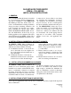
GAS INFRA-RED TUBE HEATER SEM(U) / IT(U) SERIES INSTALLATION INSTRUCTIONS 1. GENERAL It is recommended that this heater be installed by a professional gas heating equipment service person. Installation of the SEM(U)/IT (U) Series gas-fired tube heaters must conform to all manufacturers heating installation design procedures including ventilation. All local, provincial and national code requirements including the current latest edition B149.1-00 INSTALLATION CODE” in Canada, and ANSI Z223.1 in the U.S.A.
TABLE 1: MODEL CONFIGURATIONS OVERALL HEATER LENGTH SEM / IT 200-70 69’ 4” SEM / IT 200-60 59’ 8” BTU/HOUR INPUT 0 TO 4500 FT ABOVE SEA LEVEL TURBULATOR REQUIRED LENGTH GAS PRESSURE & ELECTRICAL SHIPPING WEIGHT (LBS.) 10’ LINE MINIMUM 5" W.C. N.G. 11" W.C. L.P.
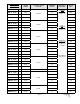
BURNER & TUBE KIT ASSEMBLY CHART MODELS: SEM & IT: Commercial / Industrial Applications TUBE KIT PART # & QUANTITY REQUIRED Stand-Alone Kits BURNER KIT FIRING RATE 60,000 80,000 100,000 110,000 130,000 155,000 175,000 200,000 Heater Tube Length 20' 30' 20' 30' 40' 20' 30, 40' 50' 30, 40' 50' 40' 50' 60' 50' 60' 70' 50' 60' 70' TM-1020SX TM-1420SX Primary Kits TM-1430SX TM-1040SX TM-F030SX TM-1030SX Secondary Kits TM-0020SX TM-0030SX 1 1 1 1 1 1 1 1 1+ 1 1+ 1 1+ 1 1 1 1 1+ 1 1+ 1
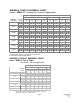
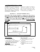
5. PRE-INSTALLATION SURVEY The SEM(U) / IT(U) heating system must have gas piping of the correct diameter, length, and arrangement to function properly. For this reason, a layout drawing is necessary. Carefully survey area to be heated, and for best results, whenever possible, place burner and combustion chamber in coldest area. 6. MOUNTING CLEARANCES This heater must be mounted and positioned to maintain the minimum clearance to combustible materials as shown in FIGURE 1 & TABLE 3.
TABLE 3 MINIMUM CLEARANCES TO COMBUSTIBLES SUSPENDED AT AN ANGLE UP TO 45 DEGREES SUSPENDED HORIZONTALLY MODEL TOP SIDE BELOW TOP REAR FRONT BELOW A B C D E F G SEM/IT 200 7" 22" 68" 7" 1" 57" 68" SEM/IT 175 6.5" 20" 68" 6.5" 1" 47" 68" SEM/IT 155 6" 19" 64" 6" 1" 44" 64" SEM/IT 130 4" 11" 60" 5" 1" 35" 56" SEM/IT 110 3" 9.5" 60" 4.5" 1" 26" 54" SEM/IT 100 7" 22" 68" 7" 1" 57" 68" SEM/IT 80 2.5" 6" 42" 3.5" 1" 23" 38" SEM/IT 60 2.
7. SYSTEMS INCORPORATING 90° ELBOWS The 90° elbows are shipped as a kit with one clamp and two end caps to close off the reflector ends each side of the elbow (s). The Reflectors must be secured with four screws to each of the end caps. (see FIG 10) The SEM / IT Series radiant tube heater can be installed in configurations as illustrated in Fig:2 (below) with a maximum of two 90° elbows per heater. The use of radiant elbows reduces the total maximum vent allowable. (See SECTION: 11) Flue Venting.
8. SUSPENSION SYSTEM The system configuration and available support locations must be considered in order to locate the radiant tubes correctly. Labour and material can be reduced by locating (system configuration permitting) directly under structural members such as joists, steel or wood beams, etc. Chain is recommended for hanging the tube system, connecting the hangers to beam support as illustrated in FIGURE 3 (below).
FIGURE 4A SEM / IT MODELS TYPICAL HANGER & SUPPORT SPACING 4” SUSPEND ALL TUBES BY TWO (2) HANGERS PER 10’ LENGTH, MOUNTED APPROX. 6” to 12” IN FROM EACH TUBE END.
FIGURE 5 ‘U’ TUBE MODELS ‘U’ TUBE HANGER FIGURE 5A TURN BOX FIGURE 5B 1 FIGURE 6 BOLTING BURNER TO FLANGED TUBE 2 3 4 • • • • • Eye Hook Fifth Nut (Holds Inner Burner to Housing) Lock Washers (4) Four Nuts (4) Four Note: Nuts may be shipped c/w lock-washers as one piece Insert four burner bolts through the tube flange, secure tightly with lock washers and nuts.
9.2. 175,000 & 200,000 Btuh INPUTS - FIRST TUBE JOINT CONNECTION Models with inputs 175,000 & 200,000 Btuh have alumatherm as the first section with a welded Flange, the second section is unpainted aluminized steel. The second tube has two slots in the un-swaged end, and fastens to the first tube using an Accu-Seal clamp (SEE FIGURE 8). The final position of the Accu-Seal clamp is flush to the end of the second tube with the ‘reaction block’ located in the center of the two slots in the tube.
10. REFLECTOR INSTALLATION SEM / IT: After burner and tubes have been installed, slide the reflectors one at a time into the wire hangers. As each successive reflector is installed on an in-line installation, the ends of the reflectors will overlap to provide continuous coverage over the entire tube system. The overlapping joints MUST BE FASTENED TOGETHER with a sheet metal screw. Note that for both horizontal and angle mounting, the tube must be level.
FIGURE 10 MOUNTING REFLECTOR END CAP 2 1 2 1 3 4 4 Reflector End Cap Flange protruding over and under the Reflector Screws securing Reflector to End Cap Opening for Tube Focus Shield Reflector 3 TABLE 4 MODEL TURBULATOR LENGTH (IF REQUIRED) TURBULATOR LENGTH (IF REQUIRED) SEM/IT 110-40 10' SEM/IT 200-70/60/50 10’ SEM/IT 110-30 14' SEM/IT 175-70/60/50 10’ SEMU/ITU 110-20 10’ not required SEMU/ITU 110-15 14’ MODEL SEM/IT 155-60/50 10' SEM/IT 100-20 10’ S/S SEMU/ITU 155-30 not re
FIGURE 13 REFLECTOR EXTENSIONS KIT- JS-0509-KT (OPTIONAL - IF REQUIRED ) 10” • • Using “S” Hooks attach the two Reflectors.
11. FLUE VENTING THIS SEM(U) / IT(U) SERIES IS APPROVED FOR BOTH DIRECT AND INDIRECT VENTING APPLICATIONS. THE SYSTEM MUST NOT BE OPERATED WITHIN A NEGATIVE AIR CONDITION, UNLESS COMBUSTION AIR IS BROUGHT IN FROM OUTSIDE DIRECTLY TO THE BURNER.
The heater is designed to operate with single wall 4” diameter 26 gauge minimum exhaust vent. When venting horizontally, the flue vent system should slope downwards approximately 1/4" per foot toward the vent terminal, start- ing at the termination of the radiant tube. When vent and combustion air are taken through the roof, the exhaust vent should always terminate higher than the combustion air intake, to prevent recycling the products of combustion back into the heater.
Where the vent pipe passes through areas where the ambient temperature is likely to produce condensation of the flue gases, the vent pipe shall be insulated with a suitable material as approved and specified by the insulation manufacturer. Check with the manufacturers Technical Support as to the maximum vent temperature requirements. The vent system must always be adequately supported to prevent sagging.
Do not install filters on the combustion air intake. For ease of installation, this heater has an optional fresh air intake duct hood. It can be used as an outdoor intake hood to bring combustion air to the heater from outside. If drawing in fresh air from outside, it is recommended as per common Engineering practice, that any single wall pipe exposed to cold air must be insulated to prevent condensation.
DO NOT use pressures greater than 1/2 psig. to pressure check the heater. TEST FOR LEAKS: All gas piping and connections must be tested for leaks after the installation is completed. Apply soap suds solution to all connections and joints and if bubbles appear, leaks have been detected and must be corrected. DO NOT USE A MATCH OR OPEN FLAME OF ANY KIND TO TEST FOR LEAKS. NEVER OPERATE THE HEATER WITH LEAKING CONNECTIONS.
14. HEATER EXPANSION Due to the characteristics of tube heaters, the installer must allow for 1” expansion for every 10’ length of tube. In order to address this characteristic, it is suggested that the gas line, flue vent, and combustion air intake (if used) be installed in such a manner, that normal expansion of the heater will be accommodated.
15. ELECTRICAL AND THERMOSTAT WIRING (SEE WIRING DIAGRAM) Wiring must be done in accordance with local codes. The total load of all heaters must be considered in determining the required contact rating of the controlling thermostat or switch. Each individual tube heater requires 120 Volts 60 Hz electrical power sized for 145VA. The heater can be controlled by a line voltage thermostat or "ON/OFF" switch. WARNING: The heater must be electrically grounded in accordance with the current Electrical Code.
17. SEQUENCE OF OPERATION / FLAME RECOVERY/ SAFETY LOCKOUT Start up - Heat Mode Flame Failure of Established Flame When the thermostat is set above the ambient temperature, 120 VAC is supplied to the L1 terminal. When this occurs the control will power up and perform a self-check routine and begin a pre-purge*, if selected. Following the pre-purge, the gas valve is energized and sparks commence until flame is detected or the Trial For Ignition (TFI) period expires.
18. LIGHTING INSTRUCTIONS LIGHTING SEQUENCE: Refer to the lighting instructions on the outside cover of the burner housing. Again, if the unit goes off on safety, main power to the unit must be manually interrupted for a 30 second reset period before the heater can be restarted. NOTE: On initial installation, the unit may lock out on safety owing to the length of time required to bleed air from the gas piping system. • • • • • • Rotate gas valve knob to ON position. Set Thermostat to the desired setting.
20.
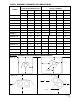
21. CA SERIES: TROUBLESHOOTING GUIDE - 120v THERMOSTAT SET THERMOSTAT TO CALL FOR HEAT CHECK FOR LINE VOLTAGE POWER SUPPLY. CHECK FOR VOLTAGE AT BLOWER MOTOR IF VOLTAGE IS PRESENT, REPLACE MOTOR. COMBUSTION AIR BLOWER STARTS NO YES NO VOLTAGE AT PIN 4 - CHECK THERMOSTAT CHECK WIRING CONNECTION, FUSE / CIRCUIT BREAKER.
CONTINUED FROM PREVIOUS PAGE MAIN BURNER LIGHTS YES NO SPARK STOPS WHEN BURNER LIGHTS YES NO SPARK IGNITER MAY BE OUT OF POSITION CHECK ELECTRICAL CONNECTION FROM IGNI TION CONTROL PIN #2 TO GAS VALVE. CHECK FOR 110 VAC ACROSS GAS VALVE IF OKAY, REPLACE GAS VALVE. CHECK GROUND WIRE, IGNITER AND HT CABLE. CHECK THAT BURNER FLAME COVERS ELECTRODE IF CHECKS ARE OKAY, REPLACE IGNITION CONTROL NOTE: IF IGNITION CONTROL GOES INTO LOCKOUT, MODE RESET THE SYSTEM.
22. SPARK IGNITION CIRCUIT The step-up transformer in the ignition control provides spark ignition at 30,000 volts (open circuit). To check the spark ignition circuit, proceed as follows.
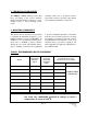
23. START-UP SHEET COMMISSIONING REPORT AS PER I&O MANUAL AND LOCAL CODES CONTRACTOR NAME: ................................................................................DATE................................ ADDRESS:............................................................................................................................................ .........................................................................................................................................................
TO BE COMPLETED BY THE LICENSED INSTALLER TUBE HEATER COMMISSIONING REPORT TYPE OF GAS: NG LP DOES BUILDING HAVE A NEGATIVE CONDITION: YES NO IF THIS IS A HIGH ALTITUDE AREA WHAT IS THE ALTITUDE ABOVE SEA LEVEL Feet DOES APPLICATION REQUIRE FRESH AIR TO BURNER YES NO IS HEATER EXPOSED TO CHEMICAL OR CORROSIVE ATMOSPHERE: YES NO ARE ACTUAL MINIMUM CLEARANCES AS PER TABLE 3 YES NO CAN HEATER BE AFFECTED BY OVERHEAD CRANES / VIBRATION YES NO ARE GAS SUPPLY LINES ADEQUATELY SIZED FOR SYSTEM
24.
Fresh Air Intake Adapter JS-0532-SE Fresh Air Intake Cap JS-0532-VC Flexible Gas Connector (USA) Input- 155,000 or less: JL-0771-FF 1/2”x18” JL-0771-XX 1/2”x24” Input- 175,000 or more: JL-0771-ZZ 3/4”x24” Type 1 Hose Gas Connector (Canada) JL-0771-RC B 45 to 155,000 Btuh, 1/2” x 36” Hose 1/2” x 36” MPT x 1/2” MPT JL-0771-RC JL-0771-RB B 175 to 200,00 Btuh, 3/4” x 36” Hose 1/2” MPT x 3/4” MPT JL-0771-RB Line Voltage Thermostat JL-0772-XX Page 30 GP-MSEM-BX-06A SEM(U) / IT(U) Manual RD: Aug 2006
TruTemp Thermostat (Do Not use in wet or corrosive environments) JM-0150-XX Low Voltage Digital Thermostat (24 Volts - °F or °C) JS-0569-WR For 24V Thermostat Control: Field Installed Transformer/ Relay Single Heater per 24v thermostat JM-0568-KT Transformer / Relay (for 2 to 7 heaters per zone) JM-0303 –KT #8 Hanging Chain - (box of 50 ft) JL-0798-JL Page 31 GP-MSEM-BX-06A SEM(U) / IT(U) Manual RD: Aug 2006 RL: 06A KH
90 degree Aluminized Steel Elbow Kit* (*Kit includes: elbow, coupler, and two end plate hangers) JS-0508-SM 180 degree Aluminized Steel Elbow Kit* (*Kit includes: elbow, coupler, and two end plate hangers) JS-0513-SM Touch Up Paint High Temp, 369g aerosol can JA-0587-XX Side Reflector Extension Kitl0” deep, l0 ft long Each JS-0509-KT Tube Protection Screen -5 feet long JA-0780-XX Page 32 GP-MSEM-BX-06A SEM(U) / IT(U) Manual RD: Aug 2006 RL: 06A KH
25.
GP-MSEM-BX-06A SEM(U) / IT(U) Manual RD: Aug 2006 RL: 06A KH
LIMITED WARRANTY CERTIFICATE FOR GAS-FIRED INFRA-RED LOW INTENSITY TUBE TYPE HEATERS : SEM(U) / IT(U) & SER / IR SERIES The Manufacturer warrants that this product is free from defects in material or workmanship under normal use and service subject to the terms of this document.