bistroSchwank Series Series Models: Models: 2135; 2150; 2152* IO-135; IO-150; IO-152* All models constructed with Marine Grade Stainless Steel Cabinet * Two-stage Model 2152 / IO-152 is natural gas only Approval: Patio Heater for Outdoor Commercial / Residential Application And / or: Gas-Fired High Intensity Infrared Heater for Commercial /Industrial Non-Residential Indoor Spaces INSTALLATION / OWNER’S MANUAL WARNING Improper installation, adjustment, alteration, service or maintenance can cause proper
NOTICE: The manufacturer reserves the right to make changes to equipment and specifications without obligation or notification. This publication, or parts thereof, may not be reproduced in any form, without prior written consent from the manufacturer Unauthorized use or distribution of this publication is strictly prohibited.
Models: 2135; 2150; 2152 / IO-135; IO-150; IO-152 Patio Heater for Outdoor Commercial/Residential Application and Gas-Fired Luminous [High Intensity] Infrared Heater for Commercial / Industrial Non-Residential Indoor Spaces This heater model is approved to two different heater standards: • A “Patio Heater” for Outdoor Use in Residential and Commercial/Industrial Applications • And as a “Gas-Fired High Intensity Infrared Heater” for Indoor Spaces of Commercial/Industrial Applications.
WARNING Improper installation, adjustment, alteration, service or maintenance can cause property damage, injury or death. Read and understand this installation and operation manual thoroughly prior to assembly, installation, operation or service to this appliance. This heater must be installed and serviced only by a trained gas service technician. Do not store or use gasoline or other flammable vapours and liquids in the vicinity of this or any other gas fired appliance.
WARNING Heater Expansion It is a normal condition that during heat-up and cool-down a radiant heater will expand and contract. Allowances for heater expansion must be made in the gas connection and heater suspension. Improper installation, alteration, or adjustment can result in property damage, injury or death. WARNING Gas Connection Improper installation, connection, or adjustment can result in property damage, toxic gases, asphyxiation, injury or death.
INSTALLATION AS AN OUTDOOR PATIO HEATER What is “Outdoor”?: An appliance approved for “outdoor use” may be installed with shelter no more inclusive than: • With walls on all sides, but with no overhead cover, [overhead permanently open] or • Within a partial enclosure which includes an overhead cover and no more than two side walls. These side walls may be parallel, as in a breezeway, or at right angle to each other.
Figure 1: OUTDOOR - MOUNTING CLEARANCES [Indoor Clearances Page 10] NOTE: MAXIMUM HEATER ANGLE IS 30° TO AVOID DAMAGE Note: Ensure mounting height in any location is sufficient to prevent patrons from coming in contact with heater, and clearance to combustible material is maintained. Table 1: OUTDOOR - MINIMUM MOUNTING & CLEARANCES TO COMBUSTIBLES QTY Application MODEL NO OUTDOOR Ends Under Horizontal 30° Angle E U A S T B F 2135/ IO-135 -N\L 14” 45” 13” 14” 17” 9” 60” OUTDOOR 2150/I
Table 2: SUGGESTED MOUNTING DISTANCES FOR COMFORT MOUNTING PARAMETERS *** MODEL 2135 / IO-135 35,000 Btuh MODEL 2150 / 2152 IO-150 / IO-152 50,000 Btuh A - Mounting angle Horizontal 300 Horizontal 300 H - Suggested height above deck 8’ to 10’ 8’ to 10’ 9’ to 12’ 8’-6” to 12’ S - Side distance to patio edge 4’ 0” 4’ 0” 5’ 0” 5’ 0” Y - Side distance between heaters 8’ 0” 8’ 0” 10’ 0” 10’ 0” W - Distance effective coverage 7’ 0” 8’ 0” 8’ 0” 10’ 0” Z - Front distance between heaters
WHEN INSTALLED INDOORS FOR COMFORT OR SPACE HEAT • • Also refer to “Outdoor” definition and requirements on page 16 And refer to Indoor Ventilation Requirements Section 14 WARNING Clearance to Combustibles Location of flammable or explosive objects, liquids or vapors close to the heater may cause fire or explosion and result in property damage, injury or death. Do not use, store or locate flammable or explosive objects, liquids or vapors in proximity of the heater.
Figure 3: INDOOR - MOUNTING CLEARANCES [Outdoor Clearances Page 7] NOTE: MAXIMUM HEATER ANGLE IS 30° TO AVOID DAMAGE Table 3: INDOOR - MINIMUM MOUNTING & CLEARANCES TO COMBUSTIBLES Ends Under HORIZONTAL E U A S T B F 2135 / IO-135 -N\L 14” 45” 18” 18” 20” 11” 60” 2150 / IO150 -N\L; 2152 / IO-152 -N 14” 60” 21” 23” 25” 10” 62” MODEL NO UP TO MAXIMUM 30° ANGLE The clearance to combustible material represents the minimum distance that must be maintained between the outer heater sur
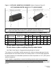
HEATER DIMENSIONS & CONFIGURATIONS Table 3: CAPACITIES & CONFIGURATIONS Voltage VAC Current amps Btu/hr input 2135 / IO-135 24 40 VA** 35,000 53 [24] 44” 2150 / IO 150 24 40 VA** 50,000 57 [26] 44” 2152 / IO 152 24 40 VA** 50,000 / 36,500 57 [26] 44” MODEL* Total Weight Length lbs.
Figure 4: MOUNTING KIT OPTIONS NOTE: MOUNT HEATER AT MAXIMUM 30° ANGLE TO AVOID DAMAGE ITEM 1: UNIVERSAL MOUNTING KIT JP-2100-CB-K Also see next page ITEM 3: ARM WALL MOUNTING KIT ITEM 2: WALL MOUNTING KIT JP-2100-MB ITEM 4: POST MOUNTING KIT JP-2300-PK JP-2300-MK Figure 5: MOUNTING OPTIONS UNIVERSAL MOUNT ARM WALL MOUNT POST MOUNT WALL MOUNT 12 2100 / IO-100 Manual IM110107 RD: AUG 2021 R.L.
JP-2100-CB-K: Universal Mounting Kit for Patio Heaters Component Quantities and Material Specifications each Kit: 2 x Ceiling/Wall Bracket - 12 ga. [0.102”] 316 S/S 2 x 24” [610 MM] Channel Leg - 12 ga. [0.102”] 316 S/S 2 x Heater Attachment Bracket - 12 ga. [0.
Figure 7: WALL MOUNT BRACKET JP-2100-MB 14 2100 / IO-100 Manual IM110107 RD: AUG 2021 R.L.
Figure 8: HEATER INSTALLATION: JP-2100-MB WALL MOUNTING KIT NOTE: MOUNT AT MAXIMUM 30° ANGLE TO AVOID DAMAGING HEATER USE BRACKET AS TEMPLATE FOR HOLES/BOLTS TO THE STRUCTURE. FASTEN TO STRUCTURAL MEMBER[S] OR DEVISE STRUCTURAL SUPPORT TO CARRY WEIGHT OF HEATER AND WIND/ SNOW LOADS FASTEN WALL BRACKET TO STRUCTURE USING FIELD SUPPLIED FASTENING HARDWARE.
JP-2300-MK ARM WALL MOUNTING KIT NOTE: MOUNT HEATER AT MAXIMUM 30° ANGLE Using pairs of holes in the heater bracket allows heater orientation: • Horizontal • Angled at 30° [MAXIMUM angle mount] Assemble Mounting Bracket to Mounting Arm using bolts and nuts supplied: • Align the anchor holes in the heater bracket and the mounting arm, and insert a bolt • Finger tighten nut on to bolt to allow rotation of the heater bracket • Align the desired mounting angle holes in the heater bracket to the outermost ho
JP-2300-PK POLE MOUNTING KIT USE CARE NOT TO DAMAGE OR SCRATCH HEATER DURING INSTALLATION FASTEN THE TWO POLE CLAMPS TO STRUCTURE USING FIELD SUPPLIED FASTENING HARDWARE.ENSURE SUFFICIENT STRENGTH AND INTEGRITY TO CARRYY WEIGHT OF HEATER AND WIND/SNOW LOADS FASTEN HEATER BRACKET TO STUDS ON TOP OF HEATER INSTALL THE TWO POLE CLAMPS ON TO WALL BRACKET USING BOLTS SUPPLIED [INSERT TOP BOLT FIRST TO CARRY WEIGHT OF HEATER] 17 2100 / IO-100 Manual IM110107 RD: AUG 2021 R.L.
1. APPLICATION: This gas-fired infrared heater is suitable for installation for heating of outdoor commercial / industrial / residential areas, and indoor commercial / industrial / nonresidential spaces. It is beyond the scope of these instructions to consider all conditions that may be encountered. Installation in the USA must conform to all local and national code requirements including the current National Fuel Gas code ANSI Z223.1, and the National Electrical Code ANSI/NFPA No 70 [latest edition].
2. INSTALLATION IN COMMERCIAL AIRCRAFT HANGARS Luminous [high intensity] radiant tube heaters are suitable for use in aircraft hangars when installed in accordance with the latest edition of the Standard for Aircraft Hangars, ANSI/NFPA No 409 in the USA, or the Canadian Natural Gas and Propane Installation Code, B149.1. A.
Installation must conform with all local, state, provincial and national code requirements including the current latest edition ANSI Z223.1 [NFPA 54] in the U.S.A. and B149.1 installation code in Canada, for gas burning appliances and equipment. The latest edition Electrical Code ANSI/NFPA N0 70 in the U.S.A. and PART 1 CSA C22.1 in Canada must also be observed. The heating system must have gas piping of the correct diameter, length, and arrangement to provide for and satisfy the total system input.
7. GAS SUPPLY PIPING • • • • • • All piping must be installed according to applicable local and national codes A listed flexible connector [field supplied] must be installed between the heater and gas supply piping. For outdoor installation the connector must be in compliance with ANSI Z21.75 / CSA 6.27. A 3/8” x 24” black finish flexible gas connector [JL-0771-OD - approved Indoor/Outdoor] is available as an option from Schwank / InfraSave.
PROPER WIRING POLARITY MUST BE MAINTAINED, particularly when grouping the heaters in a zone. Total wiring distances of up to 200' must use minimum 16 gauge electrical wire, and wiring distances of over 200' must use minimum 14 gauge electrical wire. The heater must be electrically grounded in accordance with local and national electrical codes. Malfunction of the heating system will result if the voltage varies by more than ±10% .
Heater/Zone Control Options: Locate controls in a secure staff area.
11. LIGHTING INSTRUCTIONS 1. Ensure the correct voltage is supplied, gas supply lines have been properly purged, and gas valve is switched to the ON position. 2. Turn on power to heater [high or low rate for 2-stage heater], set thermostat [if applicable] to above ambient temperature, the heater will light. 3. If heater does not light: Turn off power to heater, turn gas valve to OFF position. 4. Wait for five minutes and repeat steps above.
13. SERVICING GUIDE [Also refer to Troubleshooting Guide on page 38] Servicing of heater is essential for continued efficient operation. Servicing should be carried out annually by a qualified gas service technician as follows: • Clean the ceramic tiles with compressed air. Avoid directing air stream at gasket material between tile and heater body. The air pressure must be lower than 20 psig. • Clean venturi tube with compressed air. The air pressure must be lower than 20 psig.
Indication of back firing: • Loud ignition noise, followed by distinct hissing sound. • Little or no visible burning on the ceramic tile surface. • Combustion is taking place inside the burner body. WARNING: If heater backfires during operation, it must be turned off immediately. Cause & remedy of back firing: • Improper gas pressure entering the venturi tube: check gas supply pressure. • Damage of a ceramic tile and or gasket: - replace damaged part.
fan should be located no more than 120 ft from the furthest heater in the zone. Sufficient air supply must be provided. Exhauster Capacity: USA: Natural or mechanical means shall be provided to supply and exhaust at least 4ft3/min/1000Btuh [0.38m3/min/kW] Natural Gas input of installed heaters [4.5ft3/ min/1000Btuh [0..43m3/min/kW] Propane input]. Some local codes may require an interlock to a dedicated exhaust fan. Consult your local code and ANSI Z223.
[Single-Stage Models ONLY] 13: 28 2100 / IO-100 Manual IM110107 RD: AUG 2021 R.L.
Single-Stage Models only 29 2100 / IO-100 Manual IM110107 RD: AUG 2021 R.L.
Single-Stage Models only 30 2100 / IO-100 Manual IM110107 RD: AUG 2021 R.L.
Single-Stage Models only 31 2100 / IO-100 Manual IM110107 RD: AUG 2021 R.L.
Single-Stage Models only 32 2100 / IO-100 Manual IM110107 RD: AUG 2021 R.L.
16. SEQUENCE OF OPERATION FOR FENWAL 35-60 DSI CONTROL Start up - Heat Mode: On a call for heat the Fenwal 35-60 control will reset, perform a self check routine, flash the diagnostic LED for up to four seconds. The gas valve and spark are energized commencing the trial for ignition period. When flame is detected during the trial for ignition, spark is shutoff immediately and the gas valve remains energized.
Cautions: 1. The ceramic insulator of the igniter assembly should not be in or close to the flame. 2. The electrode assembly should not be disassembled and care must be used in making minor gap adjustment. The spark electrode should have a gap spacing of 1/8”- 3/16” [3.12± 0.81 mm]. If this spacing is not correct, the assembly must be carefully adjusted. 3. Exceeding the temperature limits can cause nuisance lockouts and premature electrode failure.
18-A.
18-B. WIRING DIAGRAM: 2152 / IO-152 Two-Stage: Fenwal 35-60 DSI - see control switch wiring next page 36 2100 / IO-100 Manual IM110107 RD: AUG 2021 R.L.
18-C. WIRING DIAGRAM: Two-Stage Switch Control Further information on 2-Stage Control Switches - Page 41 37 2100 / IO-100 Manual IM110107 RD: AUG 2021 R.L.
19. TROUBLESHOOTING GUIDE *CHECK 120 V AT PRIMARY TRANSFORMER *CHECK VOLTAGE OUT AT SECONDARY. *IF THERE IS NOT 24V TO SECONDARY.... .......REPLACE THE TRANSFORMER TURN HEATER ON NO YES 24 VOLTS ±10% TO DSI CONTROL *CHECK 24V WIRING FROM TRANSFORMER TO IGNITION CONTROL / AND CHECK IF CORRECT GAUGE OF WIRE FOR DISTANCE. *REPLACE WIRES IF NECESSARY. NO YES 24 VOLTS OUT FROM CONTROL *CHECK FOR 24 VAC ACROSS GAS VALVE TERMINALS ON CONTROL. IF NO VOLTAGE, .........REPLACE CONTROL.
MAIN BURNER LIGHTS NO YES SPARK STOPS WHEN BURNER LIT. NO YES DOES FLAME REMAIN STABLE AFTER THE SPARK CYCLE IS COMPLETE. [NO FLAME FAIL] NO YES SYSTEM RUNS UNTIL CALL FOR HEAT ENDS NO YES CALL FOR HEAT ENDS; SYSTEM SHUTS OFF NO TROUBLE SHOOTING ENDS *CHECK FOR CORRECT MANIFOLD GAS PRESSURE *CHECK FOR OBSTRUCTION IN GAS SUPPLY OR ORIFICE [INSECTS, SPIDERS COCOONS ETC.] CHECK FLAME SIGNAL WITH METER FOR 0.7µA. IF READING IS LOW CHECK GAS PRESSURE, IF OK CHANGE SENSOR.
20. COMMISSIONING REPORT This heater has been factory fired and tested prior to shipment. However, it is not a ’Plug-in’ appliance. Commissioning and field adjustment to correct settings is required.
HEATER COMMISSIONING TECHNICAL REPORT TYPE OF GAS NG LP HEATER IS EXPOSED TO CHENICAL OR CORROSIVE ATMOSPHERE YES NO OPEN COMBUSTION IS COMPATIBLE WITH THE INSTALLED LOCATION YES NO MINIMUM CLEARANCES CONFORM TO REQUIREMENTS OF THIS MANUAL YES NO WHAT IS THE ALTITUDE OF THIS PROJECT LOCATION ABOVE SEA LEVEL IS ALTITUDE ADJUSTMENT REQUIRED? [See Section 21 next page] FEET YES NO THE HEATER IS INSTALLED LEVEL ON THE LONG AXIS YES NO THE GAS SUPPLY PIPING IS ADEQUATELY SIZED FOR SYSTEM VOLU
21. HIGH ALTITUDE INSTALLATION / DERATION This heater not to be installed at altitude above 6,800 feet. USA: The factory installed orifice for this appliance is approved for altitudes zero to 2000 feet above sea level. When installed above 2000 feet, refer to information below. Canada: The factory installed orifice for this appliance is approved for altitudes zero to 4500 feet above sea level. When installed above 4500 feet, refer to information below.
22.
Heater Mounting Hardware Options - Refer to pages 11 to 17 for details NOTE: MOUNT HEATER AT MAXIMUM 30° ANGLE TO AVOID DAMAGE JP-2100-CB-K UNIVERSAL MOUNTING KIT Mounts directly to top of the heater. Allows rotation of the channel arm up to 45° from ceiling/wall bracket, and/or mounting to a sloped ceiling.
23.
REPLACEMENT PARTS LIST # 2135 / IO-135 2150, 2152 / IO-150, IO-152 PART # PART # Each JP-2100-RS JP-2100-RS ORDER QUANTITY PART NAME 13 INTERIOR REFLECTOR/HEAT SHIELD 2100 [ONE EACH SIDE] 16 LIQUID TIGHT FITTING PGB9 1 JP-2036-XX JP-2036-XX 18 HORIZONTAL SPACER PLATE 2100 1 JP-2135-HP - 19 INTERIOR BURNER END PLATE 2100 1 JP-2100-IE JP-2100-IE 21 PATIO GROMMET INLET GAS 1/2” 1 JP-2101-XX JP-2101-XX 22 90 DEGREE ELBOW 1/2”F X1/2”F 1 JS-0587-XX JS-0587-XX 23 90 DEGREE STR
STANDARD BLACK FINISH - ENCLOSURE PARTS ORDER QUANTITY 2135 / IO-135 2150, 2152 / IO-150, IO-152 PART # PART # # PART NAME 1 HANGING SUPPORT BRACKET 2100 [316 SS] PAINTED 1 JP-2100-HS-SP JP-2100-HS-SP 3 LEFT EXTERIOR PANEL 2100 [316 SS] PAINTED 1 JP-2100-RP-LSP JP-2100-RP-LSP 4 BURNER END PLATE 2100 [316 SS] PAINTED 1 JP-2100-EP-SP JP-2100-EP-SP 14 RIGHT EXTERIOR PANEL 2100 [316 SS] PAINTED [ACCESS READY] 1 JP-2100-RP-RAP JP-2100-RP-RAP 15 COMPONENT END FIXEDPLATE 2100 [316 S/S]
LIMITED WARRANTY CERTIFICATE GAS-FIRED INFRA-RED PATIO HEATERS: 2100, 2100-SS, 2152; IO-100, IO-100-SS, 10-152 SERIES The Manufacturer warrants that this product is free from defects in material or workmanship under normal use and service subject to the terms of this document.