
Manual


2100 / IO-100 Manual
IM110107
RD: AUG 2021
R.L. 11A
20
6. INSTALLATION REQUIREMENTS
6.1 MOUNTING CLEARANCES
Series 2100 / IO-100 Heaters must be mounted with minimum clearances to combustible ma-
terials. Refer to the introductory section “Clearance to Combustibles” page 6 and to Table 1
and Figure 1 page 7.
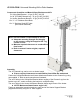
THIS HEATER HAS HOT SURFACES: Minimum mounting height is to be no less than 96”
above the floor / deck to the bottom of the heater. Do not locate heater where patrons can
come into contact with heater. Do not store or place items directly underneath heater. Main-
tain clearance to combustibles.
The heater must be located with respect to building construction and equipment so as to pro-
vide sufficient clearance and accessibility for servicing of burner and ignition control and
cleaning . Provide adequate clearance around air openings into the combustion chamber.
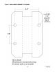
6.2 HEATER MOUNTING
Refer to Table 2 and Figure 2. Series 2100 / IO-100 Heaters are approved for both horizon-
tal and angle mounting on the short axis. A maximum 30° mounting angle is allowed to
prevent damage to the heater. Improper angle mounting can result in damage to the
heater or unsafe operation, and will void warranty.
IMPORTANT: For either horizontal or angle mounting, the long axis of the heater must be
level. Use only non-combustible mounting hardware and maintain at least the minimum clear-
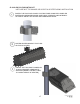
ances to combustibles. Also see Pages 11 to 17 and Figures 4 & 5 on Page 12 that illustrate
typical suspension hardware that may be used. Mounting kits can be provided by Schwank as
an optional component.
Installation must conform with all local, state, provincial and national code requirements in-
cluding the current latest edition ANSI Z223.1 [NFPA 54] in the U.S.A. and B149.1 installa-
tion code in Canada, for gas burning appliances and equipment. The latest edition Electrical
Code ANSI/NFPA N0 70 in the U.S.A. and PART 1 CSA C22.1 in Canada must also be ob-
served.
The heating system must have gas piping of the correct diameter, length, and arrangement to
provide for and satisfy the total system input. A layout drawing is necessary to calculate
properly sized gas supply piping.
Handle heater with care during installation and service to avoid scratching or damag-
ing the surface finish.
NOTE: MOUNT HEATER AT MAXIMUM 30° ANGLE TO AVOID DAMAGE
THE HEATER MUST BE RIGIDLY MOUNTED TO THE STRUCTURE TO
PREVENT WIND FORCE MOVEMENT.