
Manual
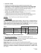


2100 / IO-100 Manual
IM110107
RD: AUG 2021
R.L. 11A
23
• Install gas and electrical supplies according to all local and national codes
• Mount heater up to a maximum of 30° angle on short axis using non-combustible mount-
ing hardware. Refer to pages 9 to 13 in this manual for information on mounting options.
• Observe all minimum clearances as indicated in Table 1 and Figure 1
• Suggested mounting distances for comfort in Table 2 and Figure 2 are guidelines based on
experience. Site conditions can allow for some deviation from these distances.
WARNING: The heater must be rigidly mounted to the structure to prevent wind force
movement.
Mounting Bracket anchoring to the structure must be of sufficient strength,
integrity and workmanship, to support the weight of the heater and any additional
loads such as wind force and snow. Mount heater up to a maximum 30° angle.
• If possible heat from two or more sides of control zones to provide most uniform comfort
• Connect heater to the main gas line. An approved 1/2" flexible connector [field supplied -
available as an option from the manufacturer] may be used to absorb heater and gas line
expansion and any vibration - check local code requirements.
• Check gas line for leaks by using soap test or gas meter test. Ensure gas pressure meets
the requirements outlined in Section 7.1 [above].
WARNING: When testing the main gas line pressure up to 0.5 psig, ensure that the
isolation valve and combination gas valve are "OFF", otherwise damage to the com-
bination gas valve will result. When testing main gas line in excess of 0.5 psig
the appliance and shut off valve must be disconnected or isolated from the gas sup-
ply piping system during any such pressure testing. Gas supply to the heater must be
regulated to be maximum 0.5 psig [14”w.c.] and minimum values listed in Table 3 above in
Section 7.1
• All wiring must comply to local and national codes. The heater requires 24Vac power sup-
ply. The heater system zone requires a field supplied 120/24Vac transformer rated at 40VA
for the first heater plus 20VA for each additional heater in the zone. Ensure proper electrical
rating in the system by checking voltage at ignition module terminals. To avoid system mal-
function, the voltage must be within 10% of required 24Vac [21.6 Volts to 26.4 Volts], and
correct polarity must be maintained throughout the system.
• Test-fire heating system - follow lighting instructions listed below and/or on the heater label.
10. INSTALLATION PROCEDURES
Heater/Zone Control Options: Locate controls in a secure staff area.
Single-Stage Models: 2135 / 2150; IO-135 / IO-150
• On/Off power switch
• patioControl Panel: Manual control by staff; JM-0204-NT up to 4 heater zones;
JM-0208-NT up to 8 heater zones; JM-0212-NT up to 12 heater zones
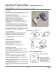
• Wireless remote control: refer to section 15 page 23
• ThermoControl Plus: Radiant temperature control of the zone system
Two-Stage Model: 2152; IO-152
• Two-Stage illuminated switch Gang assemblies [see page 43]
• ThermoControl Plus: Radiant temperature & staging control of the zone system