Models P40U, P40U-F, P40U-P, P40U-W & LOW INTENSITY TUBE TYPE INFRA RED HEATERS Models P40U-I, P40U-I-F, P40U-IP, P40U-IW LOW INTENSITY TUBE TYPE INFRA RED HEATERS INSTALLATION / OWNER’S MANUAL WARNING Improper installation, adjustment, alteration, service or maintenance can cause property damage, injury or death. Read the installation and operating and maintenance instructions thoroughly before installing or servicing this equipment.
NOTICE: This manual is current for this product. Occasional revision of the product Certification Standard may require changes to the product and/or this manual. This publication, or parts thereof, may not be reproduced in any form, without prior written consent from The Manufacturer. Unauthorized use or distribution of this publication is strictly prohibited.
P40U (-P, -W) / P40U-I (-IP,-IW) SERIES GAS FIRED INFRARED LOW INTENSITY U-TUBE TYPE TABLE OF CONTENTS TOPIC IMPORTANT INFORMATION - READ FIRST ……...PAGE APPLICATION ..............................................4 20. WIRING DIAGRAM: P40U-P, P40U-W ............30 HEATER EXPANSION ...........................5, 31 21. SEQUENCE OF OPERATION P40U-P, P40U-W.....31 GAS CONNECTION ...............................5, 31 VENTING.................................................5, 26 22. GASLITER MICRO 50N DSI .
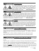
WARNImproper installation, adjustment, alteration, service or maintenance can cause property damage, injury or death. Read and understand this installation and operation manual thoroughly prior to assembly, installation, operation or service to this appliance. This heater must be installed and serviced only by a trained gas service technician. Do not store or use gasoline or other flammable vapours and liquids in the vicinity of this or any other gas fired appliance.
WARNING Heater Expansion It is a normal condition that during heat-up and cool-down a tube heater will expand and contract. Allowances for heater expansion must be made in the gas connection, venting and combustion air ducting. Improper installation, alteration, or adjustment can result in property damage, injury or death. Refer to Section 11 WARNING Gas Connection Improper installation, connection, or adjustment can result in property damage, toxic gases, asphyxiation, injury or death.
WARN- Clearance to combustibles Location of flammable or explosive objects, liquids or vapors close to the heater may cause fire or explosion and result in property damage, injury or death. Do not use, store or locate flammable or explosive objects, liquids or vapors in proximity of the heater. The clearance to combustible material represents the minimum distance that must be maintained between the outer heater surface and a nearby surface.
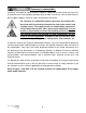
NOTE: A ‘PEEL & STICK’ SIGN IS SUPPLIED: USE AN INDELIBLE MARKER TO ENTER VALUES ON THE SIGN: ‘H’ = Calculate (instruction below) Sides of horizontal heater: ‘S’ = 24 inches (61 cm) Front of 30° Angle heater: ‘F’ = 36 inches (91.5 cm) Behind 30° Angle Heater ‘B’ = 24 inches (61 cm) POST THE SIGN ADJACENT TO THE HEATER THERMOSTAT OR IN A PROMINENT LOCATION. See next page for details.
It is the installer’s responsibility to ensure that building materials with a low heat tolerance which may degrade at lower temperatures are protected to prevent degradation. Examples of low heat tolerance materials include vinyl siding, fabrics, some plastics, filmy materials, some coatings and laminated finishes, etc. VENT END CLEARANCE: Clearances from the vent pipe are determined by local or national installation codes, but must not be less than 6 inches (15 cm).
1. LABOR REQUIRMENTS Two persons are required to safely install this equipment. SHARP EDGES - Wear gloves and other required safety protection. 2. INSTALLATION IN COMMERCIAL AIRCRAFT HANGARS Low intensity radiant tube heaters are suitable for use in aircraft hangars when installed in accordance with the latest edition of the Standard for Aircraft Hangars, ANSI/NFPA No 409 in the USA, or the Canadian Natural Gas and Propane Installation Code, B149.1. A. A minimum clearance of 8 ft (2.
WARNING Improper installation, adjustment, alteration, service or maintenance can cause property damage, injury or death. Read and understand this installation and operation manual thoroughly prior to assembly, installation, operation or service to this appliance. This heater must be installed and serviced only by a trained gas service technician. Do not store or use gasoline or other flammable vapours and liquids in the vicinity of this or any other gas fired appliance.
Proximity of lights, sprinkler heads, overhead doors, storage areas, gas and electrical lines, parked vehicles, cranes and any other possible obstruction or hazard must be evaluated. It is recommended that Protective Guard JS-0502-UR-GK be installed on any heater mounted with less than 8 feet from floor to bottom of heater (See Accessories - Page 42). 6A. SERVICE CLEARANCE: The lower ‘jaw’ of the burner cabinet swings down to provide convenient service access to burner components.
IMPORTANT: Single or multiple heater placement must be such that continuous operation of heaters will not cause combustible material or materials in storage to reach a temperature in excess of ambient temperature plus 90F° (50C°). It is the installer’s responsibility to ensure that building materials with a low heat tolerance which may degrade at lower temperatures are protected to prevent degradation.
2. Connect to the structure using mechanically sound means to support the weight. Examples of typical hardware are illustrated in FIGURE 3 below. b) If rigid hardware such as 3/8” threaded rod is used for suspension, swing joints or other means must be provided to allow for system expansion - approximately ½ inch for P40U. 3. P40U Models are packaged with the burner assembled to the tube system at the factory. For many applications a pre-assembled heater simplifies installation. 4.
FIGURE 4 TYPICAL SUSPENSION Use all four suspension points + a chain at burner eye hook. Hardware capable of supporting minimum 100 lbs (45 kg) at each suspension point. For seismic and high wind restraint see ) Sections 8-A & 8-B.
FIGURE 6 P40U MINIMUM CLEARANCES TO COMBUSTIBLES It is the installer’s responsibility to ensure that building materials with a low heat tolerance which may degrade at lower temperatures are protected to prevent degradation. Examples of low heat tolerance materials include vinyl siding, fabrics, some plastics, filmy materials, coatings, laminated surfaces, etc. Turbulators: The system is assembled at the factory with turbulators inside the tube.
8-A SEISMIC RESTRAINT - LATERAL AND LONGITUDINAL PLANES FIGURE 7 In areas prone to earthquake, or as specified on a project, install lateral and longitudinal seismic restraints as indicated in Figure 11. If the heater location can be impacted by wind (aircraft hangars, etc) refer to High Wind Restraint section 8-B below. These instructions indicate attachment of suspension and restraint hardware to the heater.
WARNING 9. FLUE VENTING Inadequate venting of a heater may result in asphyxiation, carbon monoxide poisoning, injury or death. This heater may use a vent connection or indirect venting system to remove products of combustion from the space. Seal all vent connections with high temperature sealant. Venting must be in accordance with all local, state, provincial, and national codes (ANSI Z223.1/NFPA 54 in USA; B149.1 in Canada) and as indicated below in this manual.
need to be equidistant to the vent Tee, but must comply to requirements below. The two heaters must be controlled by a single common thermostat or “ON/OFF” switch. A minimum 12 inch (30 cm) length of minimum 26 gauge single walled 4” (10 cm) diameter vent pipe is to be installed on the swaged end of the tube before any Tee or Elbow is fitted. Seal all vent connections with high temperature sealant.
Termination Cap Options: Use the approved 4" (10 cm) (JA-0528-XX) or 6" (15 cm) (JA-0529-XX) horizontal wall vent terminal (see FIGURE 20 for applicable clearances) OR a high-wind termination cap approved by a recognized certification agency (see clearance notes below) Install any termination cap a minimum of 18 inches (45 cm) from the outside wall to the inside edge of terminal opening to alleviate back pressure caused by turbulent wind conditions (See Fig. 19).
VERTICAL VENT THROUGH THE ROOF: FIGURE 11 It is the sole responsibility of the installer to adhere Approved Cap to all current local codes and/or ANSI Z223.1 / 24” CSA.B149.1 latest editions for all venting requireUp 9 60 cm ments, and practices. Approved to Use an approved ‘B-vent’ termination cap as ‘B’ Vent 12 supplied by the manufacturer of the approved ‘B-vent’.
Optional 4 inch intake terminals are available for this heater: Part number: JS-0532-VC Wall mount, bird-screened fresh air intake duct hood Part number: JS-0530-XX Roof cap Ensure adequate clearance around the air intake to allow sufficient combustion air supply to the heater. If drawing fresh air from outside, it is recommended that any single wall pipe containing cold air be insulated to prevent or reduce condensation on the pipe.
DO NOT use pressure greater than 1/2 psig to pressure check the heater. During any pressure testing of the gas piping system each heater must be isolated from the piping system by closing its individual manual shut off valve (field supplied) . IMPORTANT: Minimum supply line pressure at the inlet to the heater regulator must not be lower than 5.0 inches of water column pressure for natural gas. The supply gas pressure must be checked with all heaters in operation.
Orientation of Flexible Gas Connector (continued) FIGURE 13 12. GAS CONVERSION WARNING: Gas conversion must only be performed by a trained gas service technician. Do not convert heater to alternate gas without using one of the kits listed below. Property damage, injury or death could result. Standard production of this model heater is for use with natural gas.
13. ELECTRICAL AND THERMOSTAT WIRING (WIRING DIAGRAMS PAGE 26 & 27) NOTICE The heater must be electrically grounded in accordance with the National Electrical Code. ANSI / NFPA 70 or current Canadian Electrical code CSA C22.1. Appliance and control wiring must be in accordance with all applicable local codes. The total load of all heaters must be considered in determining the required contact rating of the controlling thermostat or switch.
17. FENWAL DSI: WIRING DIAGRAM: 24V OR 120 VOLT THERMOSTAT OPERATION 18. SINGLE FENWALHEATER DSI: WIRING 24V OR(Multiple 120 VOLT THERMOSTAT OPERATION PERDIAGRAM: THERMOSTAT Heaters per Thermostat—next page) SINGLE HEATER PER THERMOSTAT (Multiple Heaters per Thermostat—next page) NOTE: Models produced with FENWAL DSI have model designation: P40U-F & P40U-IF 18.
18. MULTIPLE TUBE HEATERS per THERMOSTAT (ALL DSI TYPES) Each tube heater requires 120V, 60 HZ electrical power sized for 145VA. Maximum power flow for internal 24V burner components is 21VA. See previous page for internal wiring. The heater must be electrically grounded in accordance with the National Electrical Code. ANSI / NFPA 70 or current Canadian Electrical code CSA C22.1. A maximum night set-back of 9°F (5°C) is recommended for optimum economy and comfort.
19. FENWAL DSI: SEQUENCE OF OPERATION / FLAME RECOVERY / SAFETY LOCKOUT Power Up / Stand By Upon applying 24 volts power to 24VAC, the control will reset, perform a self check routine, initiate full time flame sensing, flash the diagnostic LED for up to four seconds, and enter the thermostat scan state. Heat Mode When a call for heat is received from the thermostat supplying 24 volts to TH, the control checks the pressure switch for normally open contacts.
Flame Fault If at any time the main valve fails to close completely and maintains a flame, the full time flame sense circuit will detect it and energize the combustion blower. Should the main valve later close completely removing the flame signal, the combustion blower will power off following the optional post purge period. Fault Conditions The LED will flash on for 1/4 second, then off for 1/4 second during a fault condition. The pause between fault codes is 3 seconds.
Multipurpose Meter SERVICE CHECKS Flame current passes through the flame from the sensor to ground. The minimum flame current necessary to keep the system from lockout is 0.7 microamps. To measure flame current, connect an analog DC microammeter to the FC- FC+ terminals per figure at right. Use Microamp scale FC- FC+ Meter should read 0.7 µA or higher. If the meter reads below “0” on scale, meter leads are reversed. Disconnect power and reconnect meter leads for proper polarity.
20. OUTDOOR MODELS: P40U-P, P40U-W WIRING DIAGRAM: 24V OR 120 VOLT THERMOSTAT Models P40U, -I …. Page 25 SINGLE HEATER PER THERMOSTAT Multiple Heaters/Thermostat … Page 26 Maximum Power Draw = 21VA Each tube heater requires 120V, 60 HZ electrical power sized for 145VA. The heater includes a 24V/120V relay switch . Maximum power draw for internal 24V burner components is 21VA. The heater must be electrically grounded in accordance with the National Electrical Code.
21. P40U-P (-IP), P40U-W (-IW) SEQUENCE OF OPERATION GASLITER 50N (DSI) The Gasliter 50N is a three trial ignition control module with a 30 minute soft lockout/reset. It is powered by a 24v transformer that is activated when the thermostat calls for heat. On every call for heat the Gasliter 50N will delay start-up to provide a 30 second system pre-purge.
22. IGNITION CONTROL: MODELS P40U-P, -W (-IP, -IW) - GASLITER MICRO 50N The MICRO 50N is a microprocessor-based DSI (Direct Spark Ignition) control which continuously monitors the burner to ensure safe operation under all conditions. The MICRO 50N DSI Control includes specified purge and trial times, multiple ignition attempts, a diagnostic alarm output, and automatic recycle on soft lockout. The polyurethane encapsulated circuit board is suitable for damp and wet environments.
Loss of Flame - Spark Restoration Retrial If there is a loss of flame during the run mode, the unit will energize the spark within 0.8 seconds and perform a spark restoration trial for ignition. In this mode, the ignition means is restored without the gas valve being closed. If a flame is not established during the restoration trial, the unit will perform as in “No Flame Established” fault operation above.
23. SPARK IGNITER SET UP Use the following diagram to check the Igniter gap. If the gap is incorrect all adjustments should be made to the GROUND PRONG/PIN ONLY! DO NOT BEND THE IGNITER PRONG!!!! USE THE BLACK BARS BELOW AS A GUIDE FOR ADJUSTMENT. USE THE BARS THAT COINCIDE WITH THE FORMAT & SIZE OF THIS PUBLICATION . IF this manual is in 8.5” x 11” “booklet” format (pages folded in half) 3/16” 1/4” then use these bars OR IF this manual is printed 8.
24. TROUBLESHOOTING GUIDE — HEATER OPERATION — FENWAL DSI WARNING Improper adjustment, alteration, service or maintenance can cause property damage, injury or death.
MAIN BURNER LIGHTS NO CHECK FOR STRONG SPARK AT IGNITER........ (SEE PREVIOUS PAGE). YES CHECK FOR 24 VAC ACROSS GAS VALVE. CHECK OUTPUT VOLTAGE FROM CONTROL TERMINALS TO GAS VALVE.....IF NO VOLTAGE REPLACE CONTROL. CHECK ELECTRICAL WIRING, AND VOLTAGE BETWEEN IGNITION CONTROL AND GAS VALVE. IF OK, REPLACE GAS VALVE.
25. START-UP / COMMISSIONING SHEET THIS EQUIPMENT HAS BEEN FACTORY FIRED AND TESTED PRIOR TO SHIPMENT. HOWEVER, THIS APPLIANCE IS NOT “PLUG & PLAY”. IT REQUIRES COMMISSIONING AND FIELD ADJUSTMENT / SPECIFICATIONS CONFIRMATION TO ENSURE SAFE AND EFFICIENT OPERATION. COMMISSIONING REPORT AS PER I&O MANUAL AND LOCAL CODES CONTRACTOR NAME: ................................................................................DATE................................ ADDRESS:...............................................
QUALIFIED INSTALLER TO COMPLETE THIS TUBE HEATER COMMISSIONING REPORT TYPE OF GAS: NG LP DOES BUILDING HAVE A NEGATIVE CONDITION: YES NO IF THIS IS A HIGH ALTITUDE AREA WHAT IS THE ALTITUDE ABOVE SEA LEVEL Feet DOES APPLICATION REQUIRE FRESH AIR TO BURNER YES NO IS HEATER EXPOSED TO CHEMICAL OR CORROSIVE ATMOSPHERE: YES NO ARE ACTUAL MINIMUM CLEARANCES AS PER TABLE 3 YES NO CAN HEATER BE AFFECTED BY OVERHEAD CRANES / VIBRATION YES NO ARE GAS SUPPLY LINES ADEQUATELY SIZED FOR SYSTEM YES
26. DIMENSIONS AND WEIGHT Assembled System: Weight: 86 pounds (39 kg) Dimensions: 119.5” L x 20” W x 12” H (3035 mm x 508 mm x 305 mm) Burner: Weight: 26 pounds (11.8 kg) Dimensions: P40U: 16” L x 10.25” W x 10.75” H (406 mm x 260 mm x 273 mm) P40U-P,-W: 20” L x 10.25” W x 10.25” H (406 mm x 260 mm x 260 mm) Tube Reflector System: Weight: 70 pounds (27 kg) Dimensions: 103.5” L x 16.5” W x 7.
27. HIGH ALTITUDE INSTALLATION When this appliance is installed above the altitude stipulated below, the input must be de-rated by 4% for each 1000 ft . If your local utility supplies gas with a de-rated heat content, no orifice change is required in the heater . Check with your local utility regarding de-rating. USA: The factory installed orifice for this appliance is approved for altitudes zero to 2000 feet above sea level. Above 2000 feet, refer to table below.
28.
#2 Lion Chain (115 lb work load) - 200 ft roll JL-0800-XX Safety Snap Hooks - 2” - pkg of 25 JL-0800-SH JL-0800-SH-B - pkg of 100 TruTemp Thermostat True comfort control for radiant heating systems senses and averages ambient and radiant temperatures. Occupancy sensor with auto set-back of 9°F (5°C).
JS-0502-UR-GK PROTECTIVE GUARD SCREEN OPTION – Zinc Plated; Two Piece Kit – Recommended for heater mounted with less than 8 feet [2.4 m] between floor and bottom of heater or patio heating applications Two sections make up the protective guard assembly that installs on the underside of the P40-U heater. Near the bottom edge at each side of the reflector are two sets of three holes.
Fig.5 Fig. 6 STEP 4: On the second side of the reflector, first Insert a guard pin into the center hole, Fig 5. Insert remaining guard pins in the reflector holes, Fig 6. Step 5: Repeat the process with the second guard section. Hold guard screen firmly to bend pins Fig. 7 Fig. 8 Step 6: Re-install the screws at the bottom edge of the reflector into the three hangers, Fig. 7. Fig. 9 Fig. 10 (Center) Fig.
29.
Burners with FENWAL IGNITION CONTROL - Models: P40U-F; P40U-I-F 22 FENWAL DSI CONTROL REPLACEMENT KIT: FENWAL & S87J JA-0567-XX JA-0568-KT 27 IGNITION CABLE JS-0518-SA 3-Trial 24Vac with blower relay “-F” Models Fenwal Control + Wire Harness + Cable + Igniter: Replaces Fenwal & S87J Hi voltage wire (24") STW - 2 x 1/4" Spades Burners with HONEYWELL S87-J IGNITION CONTROL - Models: P40U; P40U-I 22 HONEYWELL IGNITION CONTROL REPLACEMENT KIT: FENWAL CONTROL 27 IGNITION CABLE HONEYWELL S87J # JA-0568-XX
P40U TUBE / REFLECTOR SYSTEM - ALL MODELS 25 SIGHT GLASS ASSEMBLY JS-0536-XX Sight glass assembly - tube heater 26 IGNITER KIT JA-0571-KT Spark Igniter & Gasket Kit 30 TUBE FASTENING BRACKET JS-0502-UV Positions tube in hanger / reflector system 31 PREFORMED U-TUBE JA-0501-UT Preformed U-Tube: 17 ft tube length 32 P40U HANGER JS-0506-UH P40U System Hanger 33 P40U REFLECTOR JS-0502-UR Reflector for P40U-xx 34 REFLECTOR END PLATE JS-0502-UT Reflector End Plate 35 P40U TURBULATOR
HONEYWELL S87-J WIRING DIAGRAM P40U, P40U-I : 24V OR 120 VOLT THERMOSTAT Models P40U-P, -W …. Next Page SINGLE HEATER PER THERMOSTAT Multiple Heaters/Thermostat … Page 27 Each tube heater requires 120V, 60 HZ electrical power sized for 145VA. The heater includes a 24V/120V relay switch . Maximum power draw for internal 24V burner components is 21VA. The heater must be electrically grounded in accordance with the National Electrical Code. ANSI / NFPA 70 or current Canadian Electrical code CSA C22.1.
HONEYWELL S87J: MODELS P40U, P40U-I SEQUENCE OF OPERATION The S87 ignition control module is powered by a 24v transformer and activated when the thermostat calls for heat. On every call for heat the S87J will delay start-up to provide a 30 second system pre-purge. When the S87 is activated by a thermostat or call for heat an internal transformer provides power to the electronic generator circuit for Spark Ignition and the safety lockout timing begins.
HONEYWELL S87 DSI: MODELS P40U (-I) - FLAME SENSING CIRCUIT The output of the flame sensing circuit cannot be checked directly on the S87 body. Check the flame sensing circuit directly by checking the flame sensing current from the sensor to the S87 as follows. 1. Connect a meter (dc microammeter scale) in series with the flame signal ground wire as shown below. Using the Honeywell W136A Test Meter or equivalent. Disconnect the ground wire from the S87.
LIMITED WARRANTY CERTIFICATE FOR GAS-FIRED INFRA-RED LOW INTENSITY TUBE HEATERS: P40U (-P, -W)& P40U-I (-IP, -IW) SERIES The Manufacturer warrants that this product is free from defects in material or workmanship under normal use and service subject to the terms of this document.