INSTALLATION / OWNER’S MANUAL SCHWANK GAS FIRED SEB/SEBU SERIES LOW INTENSITY TUBE TYPE INFRA RED HEATERS FOR YOUR SAFETY: FIELD CONVERTIBILITY: Do not store or use gasoline or other flammable vapours and liquids in the vicinity of this or any other appliance.
NOTICE: Schwank Inc., reserves the right to make changes to equipment and specifications without obligation or notification. All codes are current at the time of printing. This publication, or parts thereof, may not be reproduced in any form, without prior written consent from Schwank Inc. Unauthorized use or distribution of this publication is strictly prohibited. Schwank Inc. 5285 Bradco Boulevard Mississauga, Ontario, L4W 2A6 phone: (905) 712-4766 fax: (905) 712-8336 Schwank Inc.
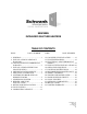
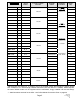
SEB/SEBU INFRA-RED GAS TUBE HEATERS TABLE OF CONTENTS TOPIC PAGE NUMBER 1. GENERAL ............................................... 1 2. INSTALLATION IN AIRCRAFT HANGARS .............................................. 1 2.1 INSTALLATION IN COMMERCIAL GARAGES................................................1 3. INSTALLATIONS OTHER THAN SPACE HEATING .................................. 1 4. PRE-INSTALLATION SURVEY ........... 3 5. MOUNTING CLEARANCES................. 3 6.
SP-MSEB-BX-10A SEB Manual RD: JUNE 2004 RL: 10 KH
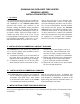
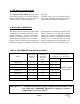
SCHWANK GAS INFRA-RED TUBE HEATER SEB/SEB(U) SERIES INSTALLATION INSTRUCTIONS 1. GENERAL It is recommended that this heater be installed by a professional gas heating equipment service person. Installation of the Schwank SEB Series gas-fired tube heaters must conform to all Schwank heating installation design procedures including ventilation. All local, provincial and national code requirements including the current latest edition B149.1 INSTALLATION CODE” in Canada, and ANSI Z223.1 in the U.S.A.
TABLE 1: MODEL CONFIGURATIONS OVERALL HEATER LENGTH * SEB 200-70 69 4” SEB 200-60 59’ 8” BTU/HOUR INPUT 0 TO 4500 FT ABOVE ** SEA LEVEL TURBULATOR REQUIRED LENGTH GAS PRESSURE & ELECTRICAL SHIPPING WEIGHT (LBS.) 10’ LINE MINIMUM 5" W.C. N.G. 11" W.C. L.P.
4. PRE-INSTALLATION SURVEY The Schwank SEB /SEBU heating system must have gas piping of the correct diameter, length, and arrangement to function properly. For this reason, a layout drawing is necessary. Carefully survey area to be heated, and for best results, whenever possible, place burner and combustion chamber in coldest area. 5. MOUNTING CLEARANCES This heater must be mounted and positioned to maintain the minimum clearance to combustible materials as shown in FIGURE 1 (PAGE 4) TABLE 3 (PAGE 4).
TABLE 3 MINIMUM CLEARANCES TO COMBUSTIBLES SUSPENDED HORIZONTALLY MODEL SUSPENDED AT AN ANGLE UP TO 45 DEGREES TOP SIDE BELOW TOP REAR FRONT BELOW A B C D E F G SEB 200 7" 22" 68" 7" 1" 57" 68" SEB 175 6.5" 20" 68" 6.5" 1" 47" 68" SEB 155 6" 19" 64" 6" 1" 44" 64" SEB 130 4" 10.5" 60" 5” 1" 35" 56" SEB 110 4" 9.5" 54" 4.5" 1" 26" 54" SEB 80 2.5" 6" 36" 3.5" 1" 23" 38" SEB 60 2.5" 5.
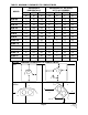
6. SYSTEMS INCORPORATING 90O ELBOWS The 900 elbows are shipped as a kit with one tube coupler. The SEB Series radiant tube heater can be installed in configurations as illustrated in Fig 2 (below) with a maximum of two 900 elbows per heater. The use of radiant elbows reduces the total maximum vent allowable. (See Section 10 Page 11: Flue Venting ) IMPORTANT: nected to the burner before any elbow.
7. SUSPENSION SYSTEM To support burner and keep it level, a separate suspension chain must be attached to the eye hook at flange end of burner angled slightly back over burner, FIGURE 4 (below). This will permit normal expansion and contraction of the tube system. (If rigid devices such as rods are used in place of chain, swing joints or other means of sufficient length must be provided to compensate for expansion.
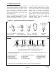
FIGURE 5 SEBU TYPICAL HANGER & SUPPORT SPACING 4” 3" 11 4" 12 4 9 1 3 6 5 10 7 2 1 8 13 "A L L T U B E S M U S T B E S U S P E N D E D B Y T W O (2 ) H A N G E R S P E R 1 0 ' L E N G T H , M O U N T E D A P P R O X IM A T E L Y 6 " T O 1 2 " IN F R O M E A C H T U B E E N D . ALL TUBES MUST BE SUSPENDED BY TWO (2) HANGERS PER 10’ LENGTH, MOUNTED APPROXIMATELY 6” TO 12” IN FROM EACH TUBE END. Exception: First and last hanger must be mounted 4” away from end of tube.
FIGURE 8 TURN BOX 8. BURNER AND TUBE INSTALLATION With all hangers suspended at the same height, insert first aluminized tube section, through 4" hole into first two wire hangers. Bolt burner to flange on first tube section, SEE FIGURE 6 (page 7). Subsequent lengths of tube can then be installed, by joining them together one inside the other and locking the joints using the aluminized steel clamp. SEE FIGURE 7 (page 7).
9. REFLECTOR INSTALLATION After burner and tubes have been installed, slide the focus shield reflectors one at a time into the wire hangers. As each successive focus shield reflector is installed on an in-line installation, the ends of the focus shield reflectors will overlap to provide continuous coverage over the entire tube system. The overlapping joints MUST BE FASTENED together. Note that for both horizontal and angle mounting, the tube must be level.
TABLE 4 TURBULATOR LENGTH (IF REQUIRED) MODEL MODEL TURBULATOR LENGTH (IF REQUIRED) SEB 200-70/60/50 10’ SEB 175-70/60/50 10’ SEB 110-40 10' not required SEB 110-30 14' SEB 155-40 10' SEBU 110-20 10’ SEBU 155-30 not required SEB 80-40 10’ SEBU 155-20 10’ SEB 80-30 14' SEB 130-50 not required SEB 80-20 14' SEB 130-40 10' SEBU 80-10 14’ SEB 130-30 14' SEB 60-30 14’ SEBU 130-20 10’ SEB 60-20 14’ SEB 110-50 not required SEBU 60-10 14’ SEB 155-60/50 NOTE: Where re
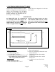
10. FLUE VENTING The SEB/SEBU series is approved for both direct vented and indirect vented applicaNOTE: 1 The system must not be operated in a negative air condition, unless combustion air is brought in from outside directly to the burner. If a severe negative pressure is INDIRECT VENTED APPLICATION When the heater is installed and indirectly vented, it is required in Canada that the heater be electrically interlocked to an independent exhaust fan by means of an Air Proving Switch.
The total maximum allowable length of vent and combustion air duct is 80' for SEB/SEBU 200, 175, 155 and 130, and 50' for SEB/ SEBU 110, 80 and 60. The total maximum allowable vent and duct is reduced by ten feet for every 90o vent elbow installed in the vent or duct. Should the system be installed with a 90 or 180 degree elbow in the radiant tube, 10ft or 20ft respectively must be deducted from the length of vent and duct. Neither the flue vent nor the combustion air duct is to exceed 50ft in length.
11. COMBUSTION AIR INTAKE DUCT Order Optional Parts: Air Intake Flange: Heater Model Required Air Intake Vent Cap: JS-0532-VC Where heater is operated in a negative air condition or in contaminated air atmosphere such as woodworking shops, air for combustion must be ducted from outside to optional intake flange on blower. The total maximum length of vent and combustion air duct is 80' for SEB / SEBU 200, 175, 155 and 130, and 50' for SEB/SEBU 110, 80 and 60.
CAUTION: If rigid gas pipe connection is made, compensation for normal gas supply pipe expansion and radiant tube expansion must be provided. All piping must conform to local codes. SEE SECTION 13: (PAGE 15) HEATER EXPANSION DO NOT use pressures greater than 1/2 psig. to pressure check the heater. TEST FOR LEAKS: All gas piping and connections must be tested for leaks after the installation is completed.
13. HEATER EXPANSION Due to the characteristics of tube heaters, the installer must allow for 1” expansion for every 10’ length of tube. In order to address this characteristic, it is suggested that the gas line, flue vent, and combustion air intake (if used) be installed in such a manner, that normal expansion of the heater will be accommodated. FIGURE 13 ALLOWANCE FOR HEATER EXPANSION TOP VIEW FLUE VENT Air Intake Vent TOP VIEW FLANGED TUBE 14.
Each individual tube heater requires 120Volts 60 Hz electrical power sized for 145VA. The heater can be controlled by a line voltage thermostat or "ON/OFF" switch. WARNING: The heater must be electrically grounded in accordance with the current Electrical Code. IMPORTANT: Do not install the thermostat in the direct radiant stream. It is good wiring practice and the installers responsibility to ensure that correct wiring polarity is maintained throughout installation.
16. SEQUENCE OF OPERATION / FLAME RECOVERY/ SAFETY LOCKOUT Start up - Heat Mode Flame Failure of Established Flame When the thermostat is set above the ambient temperature, 120 VAC is supplied to the L1 terminal. When this occurs the control will power up and perform a self-check routine and begin a prepurge*, if selected. Following the pre-purge, the gas valve is energized and sparks commence until flame is detected or the Trial For Ignition (TFI) period expires.
17. LIGHTING INSTRUCTIONS LIGHTING SEQUENCE: Refer to the lighting instructions on the inside cover of the burner housing. Again, if the unit goes off on safety, main power to the unit must be manually interrupted for a 30 second reset period before the heater can be restarted. NOTE: On initial installation, the unit may lock out on safety owing to the length of time required to bleed air from the gas piping system. • • • • • • Rotate gas valve knob to ON position.
19.
20. TROUBLESHOOTING GUIDE - 120v THERMOSTAT SET THERMOSTAT TO CALL FOR HEAT CHECK FOR LINE VOLTAGE POWER SUPPLY. CHECK FOR VOLTAGE AT BLOWER MOTOR IF VOLTAGE IS PRESENT, REPLACE MOTOR. COMBUSTION AIR BLOWER STARTS NO YES NO VOLTAGE AT PIN 4 - CHECK THERMOSTAT CHECK WIRING CONNECTION, FUSE / CIRCUIT BREAKER.
CONTINUED FROM PREVIOUS PAGE MAIN BURNER LIGHTS YES NO SPARK STOPS WHEN BURNER LIGHTS YES NO SPARK IGNITER MAY BE OUT OF POSITION CHECK ELECTRICAL CONNECTION FROM IGNI TION CONTROL PIN #2 TO GAS VALVE. CHECK FOR 110 VAC ACROSS GAS VALVE IF OKAY, REPLACE GAS VALVE. CHECK GROUND WIRE, IGNITER AND HT CABLE. CHECK THAT BURNER FLAME COVERS ELECTRODE IF CHECKS ARE OKAY, REPLACE IGNITION CONTROL NOTE: IF IGNITION CONTROL GOES INTO LOCKOUT, MODE RESET THE SYSTEM.
21. SPARK IGNITION CIRCUIT The step-up transformer in the ignition control provides spark ignition at 30,000 volts (open circuit). To check the spark ignition circuit, proceed as follows.
22. START-UP SHEET COMMISSIONING REPORT AS PER I&O MANUAL AND LOCAL CODES CONTRACTOR NAME: ................................................................................DATE................................ ADDRESS:............................................................................................................................................ .........................................................................................................................................................
TO BE COMPLETED BY THE LICENSED INSTALLER TUBE HEATER COMMISSIONING REPORT TYPE OF GAS: NG LP DOES BUILDING HAVE A NEGATIVE CONDITION: YES NO IF THIS IS A HIGH ALTITUDE AREA WHAT IS THE ALTITUDE ABOVE SEA LEVEL Feet DOES APPLICATION REQUIRE FRESH AIR TO BURNER YES NO IS HEATER EXPOSED TO CHEMICAL OR CORROSIVE ATMOSPHERE: YES NO ARE ACTUAL MINIMUM CLEARANCES AS PER TABLE 3 YES NO CAN HEATER BE AFFECTED BY OVERHEAD CRANES / VIBRATION YES NO ARE GAS SUPPLY LINES ADEQUATELY SIZED FOR SYSTEM
23.
90 degree Aluminized Steel Elbow Kit* (*Kit includes: elbow, coupler, and two end plate hangers) JS-0508-SM 180 degree Aluminized Steel Elbow Kit* (*Kit includes: elbow, coupler, and two end plate hangers) JS-0513-SM JL-0772-XX Line Voltage Thermo- 10’ Tube & Reflector Extension Kit (1-10’ Steel Tube, l-l0’Reflector, 2 Wire Hangers, 1 Coupler.
TruTemp Thermostat (Do Not use in wet or corrosive environments) JM-0150-XX Low Voltage Thermostat (24 Volts) JS-0569-XX Transformer / Relay (for 1 to 7 heaters per zone) JM-0303 –KT Fresh Air Intake Adapter JS-0532-SE Page 27 SP-MSEB-BX-10A SEB Manual RD: JUNE 2004 RL: 10 KH
Hanging Chain - (box of 50 ft) JL-0798-XX Touch Up Paint - High Temp, 369g aerosol can JA-0587-XX Tube Protection Screen -5 feet long JA-0780-XX Fresh Air Intake Cap JS-0532-VC Page 28 SP-MSEB-BX-10A SEB Manual RD: JUNE 2004 RL: 10 KH
24.
SP-MSEB-BX-10A SEB Manual RD: JUNE 2004 RL: 10 KH
LIMITED WARRANTY CERTIFICATE FOR GAS-FIRED INFRA-RED LOW INTENSITY TUBE TYPE HEATERS : SEM, SEB, SER SERIES The Manufacturer warrants that this product is free from defects in material or workmanship under normal use and service subject to the terms of this document.