INSTALLATION / OWNER’S MANUAL SCHWANK GAS FIRED Car Wash & Harsh Environment MODEL STSp-WP SERIES LOW INTENSITY TUBE TYPE FOR YOUR SAFETY: FIELD CONVERTIBILITY: Do not store or use gasoline or other flammable vapours and liquids in the vicinity of this or any other appliance.
NOTICE: Schwank Inc., reserves the right to make changes to equipment and specifications without obligation or notification. All codes are current at the time of printing. This publication, or parts thereof, may not be reproduced in any form, without prior written consent from Schwank Inc. Unauthorized use or distribution of this publication is strictly prohibited. Schwank Inc. 5285 Bradco Boulevard Mississauga, Ontario, L4W 2A6 phone: (905) 712-4766 fax: (905) 712-8336 Schwank Inc.
Car Wash & Harsh Environment STSp-WP HARSH ENVIRONMENT INFRA-RED GAS TUBE HEATERS TABLE OF CONTENTS TOPIC 1. 2.1 2.2 3. PAGE NUMBER GENERAL ............................................... 1 INSTALLATION IN CAR WASHES......... 1 INSTALLATION ON PATIOS....................1 INSTALLATIONS OTHER THAN SPACE HEATING ................................... 1 4. TUBE KIT MATRIX .................................. 3 5. PRE-INSTALLATION SURVEY .............. 4 6. MOUNTING CLEARANCES ................... 4 7.
SP-MSWP-BX-09A STSp-WP Manual RD: MAY 2004 RL: 9 KH
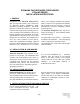
SCHWANK GAS INFRA-RED TUBE HEATER STSp-WP SERIES INSTALLATION INSTRUCTIONS 1. GENERAL Installation of the Schwank STSp-WP Series gas-fired tube heaters must conform to all Schwank heating installation design procedures including ventilation. All installations in Canada must conform to local and national code requirements including the current CSA-B149.1-00 installation code for gas burning appliances and equipment, and Canadian Electrical Code part 1 CSA C22.1 latest edition must be observed.
The following tube lengths and corresponding BTU/hr input ratings are available: CAUTION ! TABLE 1 MODELS AVAILABLE • RECOMMENDED SIZES FOR STANDARD PATIO APPLICATIONS BTU/HR INPUT O’ TO 45OO’ ABOVE SEA LEVEL OVERALL HEATER LENGTH* (FT) APPROX.
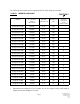
STSp-WP HEATER KIT ASSEMBLY CHART STSp-WP TUBE KIT PART # & QUANTITY REQUIRED Stand-Alone HEATER MODEL STSp 60 20 WP BURNER KIT TW1420SX JS-060P-B N/L 1 STSp 60 30 WP JS-060P-B N/L STSp 80 20 WP JS-080P-B N/L STSp 80 30 WP JS-080P-B N/L STSp 80 40 WP JS-080P-B N/L STSp 110 30 WP JS-110P-B N/L STSp 110 40 WP JS-110P-B N/L STSp 110 50 WP JS-110P-B N/L STSp 130 30 WP JS-130P-B N/L TW1430SX Primary Secondary TW1040-SX TWF030SX TW1030SX TW1010SX 1 or 1+ -> 1 1 or 1+ -> 1 TW0
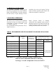
5. PRE-INSTALLATION SURVEY The Schwank STSp-WP heating system must have gas piping of the correct diameter, length, and arrangement to function properly. For this reason, a layout drawing is neces- Carefully survey area to be heated. For best results, whenever possible, place burner and combustion chamber in coldest area. 6. MOUNTING CLEARANCES This heater must be mounted with minimum clearances between the reflector surface and combustibles, as shown in FIGURE 1 (page 5), TABLE 3 (page 5).
FIGURE 1 MINIMUM CLEARANCES TO COMBUSTIBLES D A E F B C G TABLE 3 MINIMUM CLEARANCES TO COMBUSTIBLES SUSPENDED AT AN ANGLE UP TO 45 DEGREES MODEL SUSPENDED HORIZONTALLY D E F G A B C STSp200-WP 7” 1” 57” 68” 7.0” 22” 68” STSp175-WP 6.5” 1” 47” 68” 6.5” 20” 68” STSp155-WP 6” 1” 44” 64” 6.0” 19” 64” STSp130-WP 5” 1” 35” 56” 4.0” 11” 60” STSp110-WP 3.5” 1” 26” 54” 3.75” 10” 54” STSp80-WP 2.5” 1” 23” 38” 2.5” 6.0” 36” STSp60-WP 2.
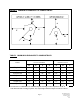
7. SYSTEMS INCORPORATING 90O ELBOWS AND 180O ELBOWS The STSp-WP Series radiant tube heater can be installed in configurations as illustrated in FIGURE 2. (below) with a maximum of two 90o or one 180o elbow per heater. The use of radiant elbows reduces the total maximum vent allowable. See FLUE VENTING in SECTION 11 (page 14). Both the 90o and 180o elbows are shipped as a kit, with one coupler kit and two end plate hangers to close off the reflector ends around the elbow(s).
8. SUSPENSION SYSTEM End plate hangers are provided to support reflectors and tubes at both ends of heater, that is at burner and at flue, see FIGURE 3 (below), FIGURES 4,5,6 (pages 7, 8). Wire hangers are provided to support reflectors and tubes along the full length between the two end plate hangers, SEE FIGURES 4,5 (pages 7, 8) and FIGURES 7,9 (page 9). The system configuration and available support locations must be considered to locate the radiant tubes correctly.
FIGURE 5 TYPICAL HANGER & SUPPORT SPACING 4" 3" 11 12 4 9 1 3 6 5 7 2 1 10 8 13 "ALL TUBES MUST BE SUSPENDED BY TWO (2) HANGERS PER 10' LENGTH, MOUNTED APPROXIMATELY 6" TO 12" IN FROM EACH TUBE END. Note Exception: First and last hanger (end plate hangers) must be mounted 4” away from end of tube 1.End Plate Hangers 2- Wire Hangers 3- Burner Assembly 4- Combustion Air Intake * ** *** **** 5.
FIGURE 7 HANGER / REFLECTOR ORIENTATION HORIZONTAL TO 450 Side ring for angle mounting at 450 degrees Side ring for angle mounting at 450 degrees Top ring for horizontal mounting Using a 1800 elbow will adapt straight tubes into a horizontal or angled “U” tube system as illustrated above FIGURE 8 SUGGESTED MOUNTING HARDWARE EYE BOLT THROUGH BEAM CLAMP HOLE IN BEAM WITH EYE SCREW EYE SCREW PIPE RING OR CLEVIS BAR-JOIST CLAMP FIGURE 9 REFLECTOR STABILIZER Note: Use the reflector stabilizer for Angle
9. BURNER AND TUBE INSTALLATION With all hangers suspended at the same height, insert first aluminized tube section, through 4" hole in first end plate hanger and onto wire hanger. End plate hanger should butt against the sight glass on the bottom of the tube, SEE FIGURE 5 (PAGE 8). Bolt burner to flange on first tube section, SEE FIGURE 10 (BELOW). Subsequent lengths of tube can then be installed, joining them together one inside the other.
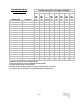
TABLE 4 TURBULATORS MODEL TURBULATOR LENGTH (IF REQUIRED) MODEL TURBULATOR LENGTH (IF REQUIRED) STSp-200-70/60/50-WP 10’ STSp-110-50-WP not required STSp-175-70/60/50-WP 10’ STSp-110-40-WP 10' STSp-155-60-WP not required STSp-110-30-WP 14' STSp-155-50-WP not required STSp-80-40-WP 10’ STSp-155-40-WP 10' STSp-80-30-WP 14' STSp-130-50-WP not required STSp-80-20-WP 14' STSp-130-40-WP 10' STSp-60-30-WP 14’ STSp-130-30-WP 14' STSp-60-20-WP 14' NOTE: Where required, the STSp-WP
FIGURE 13 MOUNTING FOCUS SHIELD REFLECTOR TO END PLATE HANGER 1 7 2 2 4 1 3 5 4 1 5 6 7 3 7 End-Plate-Hanger Flange over the Reflector End-Plate-Hanger Flange under the Reflector Screws securing Reflector to End-Plate-Hanger Chain Hole for horizontal suspension Chain Hole for up to 45º suspension Opening for Tube Focus-Shield Reflector 6 10. FOCUS SHIELD REFLECTOR INSTALLATION After burner and tubes have been installed, slide the focus shield reflectors one at a time into the wire hangers.
FIGURE 14 OPTIONAL SIDE REFLECTOR MOUNTING 10” SIDE FIGURE 15 FOCUS SHIELD REFLECTOR SLIDE 1 2 Reflector 4 3 Reflector Slide 1 FIGURE 16 HANGER ARRANGEMENTS 1 ADDITIONAL TUBE(S) 3 4 FIRST TUBE 5 Page 13 1 Two Wire Hangers per Each Middle Section 2 Use End Plate Hangers at Burner & Flue Ends (& each side of any elbow) 3 End Plate Hanger Flange UNDER Focus Shield Reflector 2 4 End Plate Hanger Flange OVER Focus Shield Reflector 5 Butt Sight Glass Ring to End Plate Hanger SP-MSWP-BX-09A STSp-WP Ma
11. FLUE VENTING NOTE: The STSp-Wp series is approved for both direct vented and indirect vented applications. The system must not be operated in a negative air condition, unless combustion air is brought in from outside directly to the burner. If a severe negative pressure is experienced or anticipated, order heater requesting custom Air Switch c/w Air Hose from Schwank. * Ensuring you specify the correct heater model number when ordering.
The total maximum allowable length of vent and combustion air duct is 80' for STSp-WP 200, 175, 155 and 130, and 50' for STSp-WP 110, 80 and 60. The total maximum allowable vent and duct is reduced by ten feet for every 90o vent elbow installed in the vent or duct. Should the system be installed with a 90 or 180 degree elbow in the radiant tube, 10ft or 20ft respectively must be deducted from the length of vent and duct. Neither the flue vent nor the combustion air duct is to exceed 50ft in length.
Where the vent pipe passes through areas where the ambient temperature is likely to produce condensation of the flue gases, the vent pipe shall be insulated. The vent system must be adequately supported to prevent sagging. FIGURE 19 FLUE VENT CONNECTION FLUE VENT END OF TUBE The end of the tube is swaged and will directly accommodate regular “C” vent and fittings for venting to outside. The “C” Vent connection to the radiant tube end must be secured with sheet metal screws.
For ease of installation, this heater has been provided with a fresh air intake duct hood. It is used as an outdoor intake hood to bring combustion air to the heater from outside. Do not use flexible dryer hose for air inlet duct. The corrugated sides of this tubing add too much restriction to the air flow and will result in heater shut down by air switches.
The supply system should be checked first with heater turned "OFF", followed by another check with heater turned "ON". DO NOT use pressures greater than 1/2 psig. to pressure check the heater. TEST FOR LEAKS: All gas piping and connections must be tested for leaks after the installation is completed. IMPORTANT: The minimum supply-line pressure at the inlet to the heater regulator must not, in any instance, be lower than 5.0 inches of water column pressure for natural gas and 11.
14. HEATER EXPANSION The Btu/hr input and the tube length determine the overall expansion that occurs in a tube system. A typical infrared tube installation will expand toward both the Burner and the vent end. In order to address this issue it is suggested that the gas line, flue vent, and combustion air intake (if used) shall be installed in such a manner, that the normal expansion of the heater will be accommodated.
15. ELECTRICAL AND THERMOSTAT WIRING (SEE WIRING DIAGRAMS PAGES 23, 26) Wiring must be done in accordance with local codes. The total load of all heaters must be considered in determining the required contact rating of the controlling thermostat or switch. Each tube heater requires 120V, 60 HZ electrical power sized for 145VA. The heater can be controlled by the Schwank Tru-Temp Thermostat, a line voltage Thermostat or by an “ON/OFF" switch.
17. LIGHTING INSTRUCTIONS NOTE: Refer to the lighting instructions on the inside On initial installation, the unit cover of the burner housing. Again, if the may lock out on safety owing to unit goes off on safety, main power to the the length of time required to unit must be manually interrupted for a 30 bleed air from the gas piping second reset period before the heater can be system. restarted. 18. RECOMMENDED MAINTENANCE 1.
19. CA SERIES SEQUENCE OF OPERATION - GASLITER MICRO 50N CA Series: The STS-p Burner with direct spark ignition, sequence is as follows : 1. Upon a call for heat by the line voltage Thermostat or "ON/OFF" switch, the Blower and the 120/24 volt Transformer are powered simultaneously with 115 volts. 7. Once the flame sensor determines there is a steady flame established, the spark igniter is then de-energized. 1a.
20.
21. CA SERIES: TROUBLESHOOTING GUIDE VOLTS APPLY 115 VOLTS—GREEN LIGHT IS ON ON 24V OPTION ONLY: THE SWITCHING RELAY ENERGIZES, SENDING 115 VOLTS TO THE BLOWER SET THERMOSTAT TO CALL FOR HEAT CHECK IF 115 VOLTS PRESENT AT BLOWER IF SO............REPLACE DEFECTIVE BLOWER COMBUSTION AIR BLOWER STARTS NO ON 24V OPTION ONLY: CHECK FOR II5V FROM SWITCHING RELAY. CHECK 24V SIDE OF RELAY VOLTAGE. CHECK 115V LINE SIDE OF RELAY VOLTAGE. CHECK OPERATION OF BOTH CIRCUITS. YES IF NO SWITCHING IS TAKING PLACE...
cont’d MAIN BURNER LIGHTS NO YES • CHECK FOR GOOD SPARK AT IGNITER..... (SEE PREVIOUS PAGE) • CHECK OUTPUT VOLTAGE FROM CONTROL TERMINALS....IF NONE REPLACE CONTROL. • CHECK FOR 25 VAC ACROSS GAS VALVE. • CHECK ELECTRICAL WIRING BETWEEN IGNTION CONTROL AND GAS VALVE.... IF OK, .........REPLACE GAS VALVE. CONTROL IS NOT SENSING FLAME WITHIN THE 21 SECOND TFI AND IS STILL TRYING TO LIGHT SPARK STOPS WHEN BURNER LIGHTS NO YES • CHECK CONTINUITY OF SENSOR CABLE AND GROUND WIRE.
22.
23. SPARK IGNITION CIRCUIT The step-up transformer in the ignition control provides spark ignition at 30,000 volts (open circuit). To check the spark ignition circuit, proceed as follows.
24. START-UP SHEET COMMISSIONING REPORT AS PER I&O MANUAL AND LOCAL CODES CONTRACTOR NAME: ................................................................................DATE................................ ADDRESS:............................................................................................................................................ .........................................................................................................................................................
TO BE COMPLETED BY THE LICENSED INSTALLER TUBE HEATER COMMISSIONING REPORT TYPE OF GAS: NG LP DOES BUILDING HAVE A NEGATIVE CONDITION: YES NO IF THIS IS A HIGH ALTITUDE AREA WHAT IS THE ALTITUDE ABOVE SEA LEVEL Feet DOES APPLICATION REQUIRE FRESH AIR TO BURNER YES NO IS HEATER EXPOSED TO CHEMICAL OR CORROSIVE ATMOSPHERE: YES NO ARE ACTUAL MINIMUM CLEARANCES AS PER TABLE 3 YES NO CAN HEATER BE AFFECTED BY OVERHEAD CRANES / VIBRATION YES NO ARE GAS SUPPLY LINES ADEQUATELY SIZED FOR SYSTEM
25.
90 degree Aluminized Steel Elbow Kit* JS-0508-SW (*Kit includes: elbow, coupler, and two end plate hangers) 180 degree Aluminized Steel Elbow Kit* JS-0513-SW (*Kit includes: elbow, coupler, and two end plate hangers) JL-0772-XX Line Voltage Thermostat Moisture Proof Thermostat JS-0570-XX Page 31 SP-MSWP-BX-09A STSp-WP Manual RD: MAY 2004 RL: 9 KH
TruTemp Thermostat JM-0150-XX (Do Not use in wet or corrosive environments) Low Voltage Thermostat (24 Volts) JS-0569-XX 24 Volt Option: Single heater per Thermostat for field mounting in Burner housings (TruTemp or 24 Volt Thermostat extra). JS-0568-KT 24 Volt Option: Multiple Heaters per Thermostat JM-0303 –KT ( for field mounting.
Hanging Chain - (box of 50ft) JL-0798-XX Touch Up Paint - High Temp, JA-0587-XX 369g aerosol can Tube Protection Screen -5 feet long JA-0780-XX Side Reflector Extension - JS-0509-XX-P l0” deep l0ft long Each 10’ Tube & Reflector Extension Kit (1-10’ Steel Tube, l-l0’Reflector, 2 Wire Hangers, 1 Coupler, 1 Reflector Stabilizer, 1 Reflector Slide) JS-0515-SW Page 33 SP-MSWP-BX-09A STSp-WP Manual RD: MAY 2004 RL: 9 KH
26.
LIMITED WARRANTY CERTIFICATE FOR GAS-FIRED INFRA-RED LOW INTENSITY TUBE TYPE HEATERS : STSp, STSpWP, STR, STSV SERIES The Manufacturer warrants that this product is free from defects in material or workmanship under normal use and service subject to the terms of this document.
SCHWANK GAS FIRED STSp-WP1 and WP2 SERIES LOW INTENSITY TUBE TYPE INFRA RED HEATERS TUBE KIT SUPPLEMENT Page 1 STSp-WP1/2 Supplement RD: NOV, 2003 RL:2 KH
STSp-W P1 HEATER KIT ASSEMBLY CHART STSp-W P-1 TUBE KIT PART # & Q UAN TITY REQUIRED Stand-Alone HEATER MODEL STSp 60 20 W P1 BU RNER KIT TW 1420S1 JS-060P-B N/L 1 STSp 60 30 W P1 JS-060P-B N/L STSp 80 20 W P1 JS-080P-B N/L STSp 80 30 W P1 JS-080P-B N/L STSp 80 40 W P1 JS-080P-B N/L STSp 110 30 W P1 JS-110P-B N/L STSp 110 40 W P1 JS-110P-B N/L STSp 110 50 W P1 JS-110P-B N/L STSp 130 30 W P1 JS-130P-B N/L TW 1430S1 Prim ary Secondary TW 1040-S1 TW F030S1 TW 1030S1 TW 1010S1 1 o
GENERAL INSTALLATION INSTRUCTIONS The following instructions are a guide to installation only, and supplement, but do not replace design instructions given in the Schwank Engineering Manual. Since most installations will differ in many details, these instructions are general. Sound judgment must be exercised and careful supervision is essential to assure that the installation will be made in the best manner possible for trouble-free operation and at the very least cost.
2. Assemble two reflector end plate hangers by attaching 1 of the reflector end plates to the hanger plate using the supplied slotted screws and nuts. If the system is longer than 10 feet, additional reflector plate hangers must be assembled. To assemble a reflector plate hanger, attach 2 of the reflector end plates to opposite sides of the hanger plate and screws using the supplied slotted screws and nuts. The reflector end plate hangers are used on each end of the total system.
3. If any of the sections of reflector need to be angled, this can be accomplished by placing the slotted screw in any of the mounting holes situated in a circular pattern. Each section of reflector can be individually adjusted independent of the previous or next shades orientation. 4. Slide the reflector end plate hangers and reflector plate hangers on the tubes before assembling the tubes. An additional coupling and reflector end plate hanger will be required for each additional tube. 5.
WARNING Installation of the turbulator is imperative to the warranty of the tubes. Install the turbulator in the last section of tubes. If installed in the first section of tube, it will cause tubes to burn out. This will void the warranty. See typical arrangements for turbulator requirements and placement.