SCHWANK GAS FIRED STSp-WP1 and WP2 SERIES LOW INTENSITY TUBE TYPE INFRA RED HEATERS TUBE KIT SUPPLEMENT Page 1 STSp-WP1/2 Supplement RD: NOV, 2003 RL:2 KH
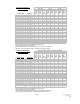
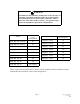
STSp-W P1 HEATER KIT ASSEMBLY CHART STSp-W P-1 TUBE KIT PART # & Q UAN TITY REQUIRED Stand-Alone HEATER MODEL STSp 60 20 W P1 BU RNER KIT TW 1420S1 JS-060P-B N/L 1 STSp 60 30 W P1 JS-060P-B N/L STSp 80 20 W P1 JS-080P-B N/L STSp 80 30 W P1 JS-080P-B N/L STSp 80 40 W P1 JS-080P-B N/L STSp 110 30 W P1 JS-110P-B N/L STSp 110 40 W P1 JS-110P-B N/L STSp 110 50 W P1 JS-110P-B N/L STSp 130 30 W P1 JS-130P-B N/L TW 1430S1 Prim ary Secondary TW 1040-S1 TW F030S1 TW 1030S1 TW 1010S1 1 o
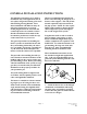
GENERAL INSTALLATION INSTRUCTIONS The following instructions are a guide to installation only, and supplement, but do not replace design instructions given in the Schwank Engineering Manual. Since most installations will differ in many details, these instructions are general. Sound judgment must be exercised and careful supervision is essential to assure that the installation will be made in the best manner possible for trouble-free operation and at the very least cost.
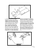
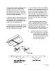
2. Assemble two reflector end plate hangers by attaching 1 of the reflector end plates to the hanger plate using the supplied slotted screws and nuts. If the system is longer than 10 feet, additional reflector plate hangers must be assembled. To assemble a reflector plate hanger, attach 2 of the reflector end plates to opposite sides of the hanger plate and screws using the supplied slotted screws and nuts. The reflector end plate hangers are used on each end of the total system.
3. If any of the sections of reflector need to be angled, this can be accomplished by placing the slotted screw in any of the mounting holes situated in a circular pattern. Each section of reflector can be individually adjusted independent of the previous or next shades orientation. 4. Slide the reflector end plate hangers and reflector plate hangers on the tubes before assembling the tubes. An additional coupling and reflector end plate hanger will be required for each additional tube. 5.
WARNING Installation of the turbulator is imperative to the warranty of the tubes. Install the turbulator in the last section of tubes. If installed in the first section of tube, it will cause tubes to burn out. This will void the warranty. See typical arrangements for turbulator requirements and placement.