Model 2300 Model IO-210 Patio Heater for Outdoor Application and Gas-Fired Luminous (High Intensity) Infrared Heater for Commercial / Industrial Non-Residential Indoor Spaces INSTALLATION / OWNER’S MANUAL WARNING Improper installation, adjustment, alteration, service or maintenance can cause property damage, injury or death. Read the installation and operating and maintenance instructions thoroughly before installing or servicing this equipment.
NOTICE: The manufacturer reserves the right to make changes to equipment and specifications without obligation or notification. This publication, or parts thereof, may not be reproduced in any form, without prior written consent from the manufacturer Unauthorized use or distribution of this publication is strictly prohibited.
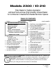
Models 2300 / IO-210 Patio Heater for Outdoor Application and Gas-Fired Luminous (High Intensity) Infrared Heater for Commercial / Industrial Non-Residential Indoor Spaces TABLE OF CONTENTS TOPIC TOPIC PAGE NUMBER IMPORTANT INFORMATION - READ FIRST 8. ELECTRICAL - BASIC REQUIREMENTS.......... 14 9. INSTALLATION PROCEDURES........................ 15 10. LIGHTING INSTRUCTIONS .............................. 16 10.1 SHUT DOWN INSTRUCTIONS................ 16 11. HEATER FINISH & APPEARANCE...................
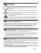
WARNING Improper installation, adjustment, alteration, service or maintenance can cause property damage, injury or death. Read and understand this installation and operation manual thoroughly prior to assembly, installation, operation or service to this appliance. This heater must be installed and serviced only by a trained gas service technician. Do not store or use gasoline or other flammable vapours and liquids in the vicinity of this or any other gas fired appliance.
WARNING Heater Expansion It is a normal condition that during heat-up and cool-down a radiant heater will expand and contract. Allowances for heater expansion must be made in the gas connection and heater suspension. Improper installation, alteration, or adjustment can result in property damage, injury or death. WARNING Gas Connection Improper installation, connection, or adjustment can result in property damage, toxic gases, asphyxiation, injury or death.
WHEN INSTALLED AS AN OUTDOOR PATIO HEATER see pages 9 - 10 for Indoor installation Also refer to “Outdoor” and “Indoor” definitions and requirements on page 11 WARNING Certain materials or items, when stored under the heater, will be subjected to radiant heat and could be seriously damaged. Location of flammable or explosive objects, liquids or vapors close to the heater may cause fire or explosion and result in property damage, injury or death.
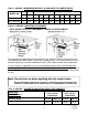
Table 1: OUTDOOR - MINIMUM MOUNTING & CLEARANCES TO COMBUSTIBLES Ends MODEL NO HORIZONTAL UP TO MAXIMUM 30° ANGLE E A S MH CH T B F MA CA 2312 / IO 212 -N\L 3” 5.5” 7” 96” 112” 9.5” 1” 9.5” 96” 113” 2313 / IO 213 -N\L 5” 7.5” 9” 102” 120” 9.5” 1.
Table 2: SUGGESTED MOUNTING DISTANCES FOR COMFORT MODEL 2312 / IO 212 23,000 Btuh MOUNTING PARAMETERS *** Horizontal A - Mounting angle MODEL 2313 / IO 213 35,000 Btuh Max. 300 Horizontal Max.
WHEN INSTALLED INDOORS FOR COMFORT OR SPACE HEAT see pages 6- 8 for Outdoor installation Also refer to “Outdoor” and “Indoor” definitions and requirements on page 11 And refer to Indoor Ventilation Requirements page 19 WARNING Clearance to Combustibles Location of flammable or explosive objects, liquids or vapors close to the heater may cause fire or explosion and result in property damage, injury or death.
Table 3: INDOOR - MINIMUM MOUNTING & CLEARANCES TO COMBUSTIBLES Ends Under MODEL NO HORIZONTAL 30° ANGLE E U A S MH CH 2312 / IO 212 -N\L 4” 60” 8” 10” 96” 114” 2313 / IO 213 -N\L 6” 60” 10.5” 14.5” 102” 123” T B F MA CA 12.5” 2.5” 14” 96” 120” 14.5” 2.
1. APPLICATION: This gas-fired infrared heater is suitable for installation for heating of outdoor commercial / industrial / residential areas and indoor commercial / industrial / nonresidential spaces. It is beyond the scope of these instructions to consider all conditions that may be encountered. Installation in the USA must conform to all local and national code requirements including the current National Fuel Gas code ANSI Z223.1, and the National Electrical Code ANSI/NFPA No 70 (latest edition).
2. INSTALLATION IN COMMERCIAL AIRCRAFT HANGARS Luminous (high intensity) radiant tube heaters are suitable for use in aircraft hangars when installed in accordance with the latest edition of the Standard for Aircraft Hangars, ANSI/NFPA No 409 in the USA, or the Canadian Natural Gas and Propane Installation Code, B149.1. A. A minimum clearance of 10 ft (3 m) above either the highest fuel storage compartment or the highest engine enclosure of the highest aircraft which may occupy the hangar.
ances to combustibles with respect to stored material, moveable objects (cranes, vehicles, lifts, overhead doors, etc), structural components, and sprinkler system heads. Consideration must also be given to ventilation fan placement (outdoor heaters do not require ventilation). Carefully survey the area to be heated, and for best results place heaters in the coldest area (s) and at sufficient spacing to provide uniform radiant heat coverage.
7. GAS SUPPLY PIPING All piping must be installed according to applicable local and national codes A listed flexible connector (field supplied) must be installed between the heater and gas supply piping. For outdoor installation the connector must be in compliance with ANSI Z21.75 / CSA 6.27. A 1/2” x 24” stainless steel flexible gas connector (JL-0771-XX - approved Indoor/Outdoor) is available as an option from Schwank / InfraSave.
PROPER WIRING POLARITY MUST BE MAINTAINED, particularly when grouping the heaters in a zone. Total wiring distances of up to 200' must use minimum 16 gauge electrical wire, and wiring distances of over 200' must use minimum 14 gauge electrical wire. The heater must be electrically grounded in accordance with local and national electrical codes. Malfunction of the heating system will result if the voltage varies by more than ±10% .
10. LIGHTING INSTRUCTIONS 1. Ensure the correct voltage is supplied, gas supply lines have been properly purged, and gas valve is switched to the ON position. 2. Turn on power to heater, set thermostat (if applicable) to above ambient temperature, the heater will light. 3. If heater does not light: Turn off power to heater, turn gas valve to OFF position. 4. Wait for five minutes and repeat steps above. If heater does not light after three attempts, call a qualified service technician. 10.
12. SERVICING GUIDE (Also refer to Troubleshooting Guide on page 29) Servicing of heater is essential for continued efficient operation. Servicing should be carried out annually by a qualified gas service technician as follows: Clean the ceramic tiles with compressed air. Avoid directing air stream at gasket material between tile and heater body. The air pressure must be lower than 20 psig. Clean venturi tube with compressed air. The air pressure must be lower than 20 psig.
Figure 4: HEATER SERVICE POSITION WITH WALL MOUNT BRACKET (To simplify illustration the heater is not shown) 18 2300 / IO 210 Manual IM110107 RD: MAY 2014 R.L.
13. VENTILATION REQUIREMENTS FOR INDOOR APPLICATION WARNING Inadequate venting of a heater may result in asphyxiation, carbon monoxide poisoning, injury or death. Heating system venting must be in accordance with all local, state, provincial, and national codes (ANSI Z223.1/ NFPA 54 in USA; B149.1 in Canada). This heater is approved for unvented (indirect venting) application.
14. HEATER DIMENSIONS & CONFIGURATIONS Table 5: CAPACITIES & CONFIGURATIONS MODEL Voltage VAC 2312 / IO 212 -NG 2312 / IO 212 -LP 2313 / IO 213 -NG 2313 / IO 213 -LP 24 Current amps 40 VA* Btu/hr input Total Weight (lbs). Length 23,000 23,000 35,000 35,000 32 32 44 44 30 1/2” 30 1/2” 43 1/2” 43 1/2” * For a multiple heater installation, the first heater is sized at 40VA and each consecutive heater is sized at 20VA. The sum total will be the required Transformer size.
Figure 6: MOUNTING KIT OPTIONS NOTE: MOUNT HEATER AT MAXIMUM 30° ANGLE TO AVOID DAMAGE ITEM 1: WALL MOUNTING BRACKET JP-2300-MB ITEM 3: POST MOUNTING BRACKET JP-2300-PK ITEM 2: ARM MOUNTING KIT JP-2300-MK CHAIN HANGING SUPPORT (SUPPLIED WITH HEATER) Figure 7: MOUNTING OPTIONS WALL MOUNT POST MOUNT CHAIN HANGING ARM MOUNT (BRACKET SUPPLIED WITH HEATER) 21 2300 / IO 210 Manual IM110107 RD: MAY 2014 R.L.
Figure 8: MOUNTING ARM WALL PLATE 22 2300 / IO 210 Manual IM110107 RD: MAY 2014 R.L.
Figure 9: WALL MOUNT BRACKET 23 2300 / IO 210 Manual IM110107 RD: MAY 2014 R.L.
Figure 10: HEATER INSTALLATION: WALL MOUNT BRACKET Wall Mount Bracket Heater Bracket 1. Install the Wall Mount Bracket on the wall, using four bolts...(field supplied). See warning note (page 16) - ensure strength and integrity of mechanical fastening to structure 2. Install the heater bracket on the heater using four nuts. 3. Install the heater bracket to the wall mount bracket, and remove the chains from the top of the heater.
16. ELECTRICAL REQUIREMENTS AND THERMOSTAT CONTROL All electrical installations must meet local and the latest edition Electrical Code PART 1 CSA C22.1 in Canada and ANSI/NFPA N0 70 in the U.S.A.. Single heater requires 24 Volt, 60 Hz electrical transformer sized at 40VA. If multiple heaters are connected to a single transformer, the proper transformer is 24 Volt, 60 Hz, sized at 40VA for the first heater, and 20VA each for all subsequent additional heaters.
Flame Failure - Re-Ignition: If the established flame signal is lost while the burner is operating, the control will respond within 0.8 seconds. The HV spark will be energized for a trial ignition period in an attempt to relight the burner. If the burner does not light the control will make two more attempts to relight the burner before de-energizing the gas valve. If the burner does not relight, the control will go into lockout as noted above in “Failure to light”.
18. SPARK IGNITION CIRCUIT The step-up transformer in the ignition control provides spark ignition at 30,000 volts (open circuit). To check the spark ignition circuit, proceed as follows.
19.
20. TROUBLESHOOTING GUIDE *CHECK 120 V AT PRIMARY TRANSFORMER *CHECK VOLTAGE OUT AT SECONDARY. *IF THERE IS NOT 24V TO SECONDARY.... .......REPLACE THE TRANSFORMER TURN HEATER ON NO YES 24 VOLTS ±10% TO DSI CONTROL *CHECK 24V WIRING FROM TRANSFORMER TO IGNITION CONTROL / AND CHECK IF CORRECT GAUGE OF WIRE FOR DISTANCE. *REPLACE WIRES IF NECESSARY. NO YES 24 VOLTS OUT FROM CONTROL *CHECK FOR 24 VAC ACROSS GAS VALVE TERMINALS ON CONTROL. IF NO VOLTAGE, .........REPLACE CONTROL.
*CHECK FOR CORRECT MANIFOLD GAS PRESSURE MAIN BURNER LIGHTS NO YES SPARK STOPS WHEN BURNER LIT. NO YES DOES FLAME REMAIN STABLE AFTER THE SPARK CYCLE IS COMPLETE. (NO FLAME FAIL) NO YES SYSTEM RUNS UNTIL CALL FOR HEAT ENDS NO *CHECK FOR OBSTRUCTION IN GAS SUPPLY OR ORIFICE (INSECTS, SPIDERS COCOONS ETC.) CHECK FLAME SIGNAL WITH METER FOR 0.7µA. IF READING IS LOW CHECK GAS PRESSURE, IF OK CHANGE SENSOR. CHECK FOR CONTINUITY OR SENSOR CABLE AND GROUND WIRE.
21. COMMISSIONING REPORT This heater has been factory fired and tested prior to shipment. However, it is not a ’Plug-in’ appliance. Commissioning and field adjustment to correct settings is required.
HEATER COMMISSIONING TECHNICAL REPORT TO BE COMPLETED BY QUALIFIED GAS FITTER INSTALLER TYPE OF GAS: NG LP IS HEATER EXPOSED TO CHEMICAL OR CORROSIVE ATMOSPHERE: YES NO IS AN OPEN FLAME COMPATIBLE WITH THE INSTALLED LOCATION: YES NO MINIMUM CLEARANCES CONFORM AS PER I&O MANUAL: YES NO IF THIS IS A HIGH ALTITUDE AREA WHAT IS THE ALTITUDE ABOVE SEA LEVEL Feet IS HEATER SHORT AXIS HORIZONTAL WITH THE VENTURI ON TOP: YES NO IS GAS SUPPLY LINE ADEQUATELY SIZED FOR SYSTEM VOLUME: YES NO HAVE G
22. HIGH ALTITUDE INSTALLATION / DERATION This heater not to be installed at altitude above 6,800 feet. USA & Canada: The factory installed orifice for this appliance is approved for altitudes zero to 2000 feet above sea level. When installed above 2000 feet, refer to information below. When this appliance is installed above the standard altitude stipulated the input must be de-rated by 4% for each 1000 ft above sea level.
23. Replacement Parts List Only the following illustrated parts are available. For any other parts please contact the manufacturer. 34 2300 / IO 210 Manual IM110107 RD: MAY 2014 R.L.
LIMITED WARRANTY CERTIFICATE GAS-FIRED INFRA-RED PATIO HEATERS: 2300 / IO 210SERIES The Manufacturer warrants that this product is free from defects in material or workmanship under normal use and service subject to the terms of this document.