
User's Manual


3
Date Code 20170317 Instruction Manual SEL-FT50/SEL-FR12 Fault Transmitter and Receiver System
System Overview
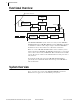
Figure 1 SEL-FT50/SEL-FR12 System
The SEL-FT50/SEL-FR12 system components are easy to use, and they
contain many powerful and innovative features. Use programmable logic in
the SEL-651R or in connected relays to incorporate the new protection
capabilities and achieve the benefits shown in Figure 1.
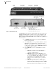
Figure 2 SEL-FT50 Overview
Each SEL-FT50 mounts onto and monitors the line current on one phase.
When a fault occurs, the SEL-FT50 transmits a high-speed wireless signal to
influence protection decisions. Control (DIP) switches inside the transmitter
allow easy selection of unit and Network IDs. No batteries are needed because
the SEL-FT50 is powered by the line current.
Protective Device
SEL-651R
SEL-FR12
SEL-FT50
M
IRRORED
B
ITS
Distribution
System
Collection Protection
Logic
• Collect wireless
signals simultaneously
from as many as 12
fault transmitters
• Monitor as many as 4
three-phase branches
SEL-FT-50/SEL-FR12
System Benefits
• Speed up protection
• Improve power quality
• Protect equipment
• Enhance safety
Hot stick loop
Current transformer
Twistlock housing
for setting access
Omnidirectional antenna for
the radio transmitter
Spring for secure installation
Conductor stop
Left control (DIP)
switch bank
SW 1–4 Unit ID
SW 5–8 Network ID
Right control (DIP)
switch bank
SW 6–8 fault pickup