
User's Manual


8
SEL-FT50/SEL-FR12 Fault Transmitter and Receiver System Instruction Manual Date Code 20170317
Application Examples
Improve Fuse-Blowing
Schemes With the
Fault Transmitter and
Receiver System
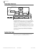
With the SEL-FT50/SEL-FR12 system installed as shown in Figure 8, the
recloser control receives an indication whenever a fault is on the unfused
branch. With this information, if a fault occurs on the unfused line section, the
recloser control can trip instantaneously instead of waiting for the fuse delay.
In Figure 8, the unfused tap is monitored by a set of SEL-FT50 Fault
Transmitters (one for each phase), one SEL-FR12, and one SEL-651R. The
SEL-FR12 is connected to the SEL-651R via a serial port.
Figure 8 SEL-FT50 on Unfused Tap
When using the SEL-FT50/SEL-FR12 system, the SEL-651R knows when a
fault occurs on the unfused tap because one or more of the SEL-FT50 Fault
Transmitters detect the fault current and send the fault status to the SEL-FR12,
which then conveys the information to the recloser control.
The SEL-651R settings replace or modify the curve behavior while the fault is
happening. In the example fault shown in Figure 8, the recloser control
enables the recloser control fast curve (see Figure 6). Compare this to when a
fault is on the same unfused line section but the recloser control does not know
it. The recloser trips after a delay. Based on the coordination curves in
Figure 6, for a 1000 A fault, using the SEL-FT50/SEL-FR12 system to trip on
the fast curve instead of the slow curve reduces the fault clearing time by
400 ms.
Fuse-Saving
Combined With Fuse-
Blowing Schemes
The fundamental choice in distribution-line protection is between fuse-saving
and fuse-blowing. For a given fault, designers either favor blowing fuses and
disrupting as few customers as possible, or tripping the recloser and
interrupting the fault without blowing any fuses. Each method has its
advantages, but the protection planner has to pick one or the other.
Using the SEL-FT50/SEL-FR12 system, design smart protection that switches
from fuse-saving to fuse-blowing, or vice versa without interruption. You get
the fuse-saving or fuse-blowing benefits you want while eliminating any
drawbacks.
The following two example applications show how a single protective zone
using the SEL-FT50/SEL-FR12 system allows both fuse-saving and fuse-
blowing schemes in service.
Example 1: Switchover Without Interruption From a Fuse-Blowing
Scheme to a Fuse-Saving Scheme
In this switchover scheme, utilities have the option to tailor protection for
specific line segments with different characteristics. If the SEL-FT50 declares
that a fault is present on a candidate line section, the scheme enables fuse-
saving while the fault is in progress. For other faulted line segments, the fuse-
blowing scheme works as intended.
R
SEL-FR12
SEL-651R-2
When the fault is on the unfused branch, the recloser trips without fuse-coordination delay.
SEL-FT50