
Instruction Manual


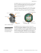


Table Of Contents
- Major Features and Benefits
- Functional Overview
- System Overview
- Application Examples
- Collect Fault Information From Remote Branches
- Improve Fuse Coordination
- Fuse-Blowing Scheme Shortcomings
- Improve Fuse-Blowing Schemes With the Fault Transmitter and Receiver System
- Fuse-Saving Combined With Fuse-Blowing Schemes
- Improve Feeder Cable First-Span Protection
- Implement a Low-Cost Fast Bus-Tripping Scheme
- Tripping the Right Recloser Faster
- Safety Information
- Network Deployment Overview
- Device Installation
- Dimensions
- Specifications
- Appendix A: Manual Versions
- Appendix B: Two-Branch Application
- Appendix C: Link Budget Analysis
- Appendix D: SEL-RP50 Fault Repeater Detailed Implementation
- Technical Support

3
Date Code 20210405 Instruction Manual SEL-FT50/SEL-FR12 Fault Transmitter and Receiver System
Functional Overview
The SEL-FT50 and SEL-FR12 contain subsystems outlined in the upper and
lower portion of Figure 1, respectively.
The SEL-RP50, outlined in the center portion of Figure 1, is available in certain
markets. Installing one or more SEL-RP50s per SEL-FT50 can mitigate obstruc-
tions that otherwise compromise the radio path.
The SEL-FT50/SEL-FR12 system consists of as many as 12 SEL-FT50 Fault
Transmitters and 1 SEL-FR12 Fault Receiver. The SEL-FT50 is mounted on dis-
tribution conductors with voltages as high as 38 kV. The SEL-FR12 is mounted
in a recloser control cabinet or in a substation control house.
When one or more SEL-FT50 Fault Transmitters detect a fault, they send a wire-
less signal to the SEL-FR12. The SEL-FR12 transfers the received signal to the
recloser control or relay via M
IRRORED BITS communications in as little as 6 ms.
The recloser control uses the fault information to make protection or relay deci-
sions.
To monitor the health of the system, the SEL-FT50 Fault Transmitters periodi-
cally send communication link-check messages to the SEL-FR12 to indicate their
status.
Each SEL-RP50 Fault Repeater forwards fault and link messages from one
SEL-FT50. Up to five SEL-RP50s can be installed in a row with proper settings,
and must be installed on the same phase conductor for proper operation in low
current conditions. The SEL-RP50s will usually be installed in sets of three, one
per phase.
The SEL-FR12 recognizes messages coming directly from SEL-RP50s and/or
indirectly via SEL-RP50s.
NOTE: Systems with SEL-FT50s
manufactured before May 2021 only
support one SEL-RP50 per SEL-FT50.
See
Appendix D: SEL-RP50 Fault
Repeater Detailed Implementation on
page 54
for required settings.