30i This product is compliant with the applicable CE requirements.
TABLE OF CONTENTS Important Safety Instructions Safety Warning Labels / Serial Number Specifications Before Assembly Parts Hardware Tools Assembly Leveling the Bike Moving the Bike Features Console Features Contact Heart Rate (CHR) 3 5 6 6 7 8 8 9 15 15 16 17 20 Operations Adjustments Initial Setup Quick Start / Manual Program User Profiles Profile Programs Pausing or Stopping Results GOAL TRACK Statistics Console Setup Mode Maintenance Troubleshooting 22 22 22 23 23 25 27 27 28 30 31 33 To validate war
IMPORTANT SAFETY INSTRUCTIONS ! This icon means a potentially hazardous situation which, if not avoided, could result in death or serious injury. Obey the following warnings: ! Read and understand all warnings on this machine. Carefully read and understand the Assembly instructions. • Keep bystanders and children away from the product you are assembling at all times. • Do not connect power supply to the machine until instructed to do so.
• Set up and operate this machine on a solid, level, horizontal surface. • Make the Pedals stable before you step on them. Use caution when you step on and off the machine. • Disconnect all power before servicing this machine. • Do not operate this machine outdoors or in moist or wet locations. Keep the foot pedals clean and dry. • Keep at least 0.6 m (24”) on each side of the machine clear.
SAFETY WARNING LABELS AND SERIAL NUMBER Serial number Product specification 5
SPECIFICATIONS Maximum User Weight: 136 kg (300 lbs.) Total Surface Area (footprint) of equipment: 5670 cm2 Machine Weight: 26.5 kg (58.4 lbs.) Power Requirements: Operational Voltage: 220V - 240V AC, 50Hz Operating Current: 0.4A 141cm (55.6”) Regulatory Approvals: ISO 20957 compliant. 105cm (41.3”) 54cm (21.4”) DO NOT dispose of this product as refuse. This product is to be recycled. For proper disposal of this product, please follow the prescribed methods at an approved waste center.
PARTS 7 8 6 16 11 14 5 9 4 15 1 10 13 (R) 2 3 12 (L) Item Qty Description Item Qty Description 1 1 Main Frame 9 1 Seat Post 2 1 Front Stabilizer 10 1 Adjustment Knob 3 1 Rear Stabilizer 11 1 Seat 4 1 Top Shroud 12 1 Left Pedal (L) 5 1 Mast Gasket 13 1 Right Pedal (R) 6 1 Console Mast (with Handlebar Mount) 14 1 Water Bottle Holder 7 1 Handlebars 15 1 AC Adapter 8 1 Console 16 1 Handlebar Mount Cover Note: M edia Cable is in a bag.
HARDWARE / TOOLS D Item Qty A 4 Button Head Hex Screw M8 x 25 B 5 Lock Washer M8 C 4 Curved Washer M8 D 1 Flat Washer M8 E 1 T-handle E Description Note: S elect pieces of Hardware have been provided as spares on the Hardware Card. Be aware that there may be remaining Hardware after the proper assembly of your machine.
ASSEMBLY 1. Attach Stabilizers to Main Frame Note: H ardware(*) is pre-installed on the stabilizers and not on Hardware Card. Make sure transport wheels on the front stabilizer point forward, and the Schwinn® decal on the rear stabilizer faces outward from the machine. 6 mm 6 mm X2 * * * * X2 * * 2. Install Console Mast, Mast Gasket and Top Shroud on Main Assembly NOTICE: M ake sure the Console Cable connector (a) does not fall into the Console Mast.
3. Install Handlebars on Console Mast NOTICE: D o not crimp the cables. Put the Handlebar (7) in the bracket (6a), adjust the Handlebar to the desired angle, and install the T-handle (E) through the holes. Use the pull cable in the Handlebar Mount to route the HR cable (7a) through the slot (6c) under the Handlebar Mount to the top of the mast. Fully tighten the T-handle to keep the Handlebar in position. Push the cover (16) into position on the Handlebar Mount.
4. Install Console on Console Mast Note: R emove the pre-installed screws(*) from the back of the Console before you connect the cables. NOTICE: D o not crimp the cables.
5. Install Seat Post on Frame NOTICE: M ake sure the Adjustment Knob engages the Seat Post. Do not set the Seat Post position higher than the stop mark (STOP) on the tube. 9 10 STOP 10 6. Attach Seat to Seat Post NOTICE: B e sure the Seat is straight. Tighten the nuts (11b) on the Seat bracket (11a) to hold the Seat in position.
7. Install Pedals Note: T he Left Pedal is reverse-threaded. Be sure to attach Pedals on the proper side of the Bike. Orientation is based from a seated position on the bike. The Left Pedal has an “L”, the Right Pedal an “R”.
8. Install Water Bottle Holder Note: T he hardware(*) is pre-installed on the Console Mast and not on Hardware Card. 14 X2 * 9. Connect AC Adapter 15 10. Final Inspection Inspect your machine to ensure that all hardware is tight and components are properly assembled. Be sure to record the serial number in the field provided at the front of this manual.
BEFORE YOU START Leveling Your Bike Levelers are found on each side of the Rear Stabilizer. Turn the knob to adjust the stabilizer foot. Make sure the bike is level and stable before you exercise. Moving Your Bike To move the upright bike, carefully tilt the Handlebars toward you while pushing the front of the bike downward. Push the bike to the desired location. NOTICE: Be careful when you move the bike. Abrupt motions can affect the computer operation.
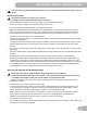
FEATURES A Q C P B A O M N L B K D E F R J G I H F A Console J Power Connector B Handlebars K Water Bottle Holder C Adjustable Seat L MP3 Input D Adjustment Knob M USB Port E Pedals N Contact Heart Rate (CHR) Sensors F Stabilizers O Speakers G Levelers P Fan H Fully Shrouded Flywheel Q Media Tray I Transport Rollers R Media Cable WARNING! U se the values calculated or measured by the machine’s computer for reference purposes only.
Console Features The Console provides important information about your workout and lets you control the resistance levels while you exercise. The Console features the Schwinn Dual Track™ display with touch control buttons to navigate you through the exercise programs.
FAN button- Controls 3-speed fan Resistance Level Quick Buttons- Shifts the resistance levels to the setting quickly during a workout Achievement Indicator Lights- when a workout result is reviewed, the achievement indicator light will activate.
8 7 6 5 4 3 2 1 Achievement Display 10% is The Achievement Display activates when a workout goal reached 40% 70% or a workout milestone is surpassed from past workouts. The Console display will congratulate and inform the User of their achievement, along with a celebratory sound. Lower Display Data Hr The Lower Display shows the Workout Values and can be customized for each User. (Consult the “Edit User Profile” section of this manual.) Use the Right() button to move through all the workout statistics.
Export Workout Results to USB Flash Drive This fitness machine is equipped with a USB Port and can export your Workout Results to a USB Flash Drive. With the Workouts exported from the fitness machine, connect the USB Flash Drive to a computer and upload the file to your Schwinn Connect™ account. Note: USB Flash Drives must be formatted in FAT32 for proper functionality. 1. From the Power-Up screen, push the User button to select the desired User Profile. 2.
Once the Console has your initial heart rate, do not move or shift your hands for 10 to 15 seconds. The Console will now validate the heart rate. Many factors influence the ability of the sensors to detect your heart rate signal: • Movement of the upper body muscles (including arms) produces an electrical signal (muscle artifact) that can interfere with pulse detection. Slight hand movement while in contact with the sensors can also produce interference.
OPERATIONS What to Wear Wear rubber-soled athletic shoes. You will need the appropriate clothes for exercise that allow you to move freely. How Often Should You Exercise Consult a physician before you start an exercise program. Stop exercising if you feel pain or tightness in your chest, become short of breath, or feel faint. Contact your doctor before you use the machine again. Use the values calculated or measured by the machine’s computer for reference purposes only.
4. Push OK to set. 5. Units of Measurement: Push the Increase/Decrease buttons to adjust between “MILES” (Imperial English) or “KM” (metric). 6. Push OK to set. The Console goes back to the Power-Up / Idle Mode screen. Note: To adjust these selections, consult the “Console Set-Up Mode” section. Quick Start ( Manual ) Program The Quick Start ( Manual ) program lets you start a workout without entering any information. During a Manual Workout, each column represents a 2 minute time period.
Edit User Profile 1. From the Power-Up Mode screen, push the Increase() or Decrease() buttons to select one of the User Profiles. 2. Push the OK button to select the User Profile. 3. The Console display shows the EDIT prompt and the current User Profile name. Push OK to start the Edit User Profile option. To exit the Edit User Profile option, push the PAUSE/END button and the console will go back to the Power-Up Mode screen. 4.
6. Push OK to make your selection. 7. The Console will go to the Power-Up Mode screen. Changing Resistance Levels Push the Resistance Level Increase() or Decrease() buttons to change the resistance level at any time in a workout program. To rapidly change the resistance level, push the desired Resistance Level Quick Button. The Console will adjust to the selected resistance level of the quick button. Profile Programs These programs automate different resistance and workout levels.
Workout Profile and Goal Program The Console lets you select the Profile Program and type of Goal for your workout (Distance, Time or Calories), and set the Goal value. 1. Sit on the machine. 2. Push the Increase() or Decrease() buttons to select the correct User profile. 3. Push the Programs button. 4. Push the Left() or Right() buttons to select a Category of Workout. 5. Push the Increase() or Decrease() buttons to select a Profile Workout, and push OK. 6.
2. Push the Increase() or Decrease() buttons to select the percentage of maximum heart rate: 50–60%, 60–70%, 70–80%, 80–90%. onsult a physician before you start an exercise program. Stop exercising if you feel pain or tightness in C your chest, become short of breath, or feel faint. Contact your doctor before you use the machine again. Use the values calculated or measured by the machine’s computer for reference purposes only.
During the Cool Down period, the Resistance Level will adjust to a third of the average Level of the workout. The Cool Down resistance level can be adjusted with the Resistance Increase and Decrease buttons, but the Console will not display the value. You can push PAUSE/END to stop the Results / Cool Down period and go back to Power-Up Mode. If there is no RPM or HR signal, the Console automatically goes into Sleep Mode.
5. Push the Increase() button to move to the “SAVE TO USB - OK?” prompt. Push OK and the “ARE YOU SURE? -NO” prompt will display. Push the Increase() button to change it to yes and push OK. The Console will display the “INSERT USB” prompt. Insert a USB Flash Drive into the USB Port. The Console will record the Statistics to the USB Flash Drive. The Console will display “SAVING”, and then “REMOVE USB” when it is safe to remove the USB Flash Drive.
CONSOLE SETUP MODE The Console Setup Mode lets you input the date and time, set the units of measurement to either English or Metric, change the machine type, control the sound settings ( on/ off), or see maintenance statistics (Error Log and Run Hours – for service technician use only). 1. Hold down the PAUSE/END button and Right button together for 3 seconds while in the Power-Up Mode to go into the Console Setup Mode.
MAINTENANCE Read all maintenance instructions fully before you start any repair work. In some conditions, an assistant is necessary to do the necessary tasks. ! Equipment must be regularly examined for damage and repairs. The owner is responsible to make sure that regular maintenance is done. Worn, damaged or loose components must be repaired or replaced immediately. Only manufacturer supplied components can be used to maintain and repair the equipment.
Maintenance Parts A K A DD J EE M L BB R C N CC Y AA B J G O H P I D Q Z X W S T D J U E C V F 32 A Console L HR Cables W Flywheel B Console Mast M CHR Sensors X Brake Assembly C Pedals N Seat Y RPM Sensor D Crank Arms O Seat Post w/ Slider Z Speed Sensor Magnet E Left Shroud P Adjustment Knob AA Servo Motor F Power Inlet Q Seat Post Shroud BB Drive Belt G Right Shroud R Water Bottle Holder CC Drive Pulley H Top Shroud S Rear Stabilizer DD
TROUBLESHOOTING Condition/Problem No display/partial display/ unit will not turn on Things to Check Solution Check electrical (wall) outlet Make sure unit is plugged into a functioning wall outlet. Check connection on console Connection should be secure and undamaged. Replace adapter or connection at unit if either are damaged. Check data cable integrity All wires in cable should be intact. If any are visibly crimped or cut, replace cable.
Condition/Problem Things to Check Solution Check data cable connections/orientation Be sure cable is connected securely and oriented properly. Reseat all connections. Small latch on connector should line up and snap into place. Check Servo Motor (requires shroud removal) If magnets move, adjust until they are within the proper range. Replace Servo Motor if not functioning properly. If the above steps do not resolve the problem, contact your local distributor for further assistance.
EN Nautilus® 8011446.060116.