Manual en Español Latino Americano: http://www.schwinnfitness.
Table of Contents Important Safety Instructions - Assembly 3 Safety Warning Labels / Serial Number 4 Specifications 4 Parts 5 Tools 5 Hardware 6 Before Assembly 6 Assembly 7 Moving the Bike 15 Leveling the Bike 15 Important Safety Instructions - Owner's 16 Features 17 Console Features 18 Remote Heart Rate Monitor 19 Operations 21 Adjustments 21 Quick Start / Manual Program 22 Workout Program Selection 22 Schwinn™ Advantage User Setup Mode 23 Profile Programs 25 Pausing or Stopp
Important Safety Instructions -Assembly This icon means a potentially hazardous situation which, if not avoided, could result in death or serious injury. Obey the following warnings: Read and understand all warnings on this machine. Carefully read and understand the Assembly instructions. • Keep bystanders and children away from the product you are assembling at all times. • Do not connect power supply to the machine until instructed to do so.
Safety Warning Labels and Serial Number / Specifications • Keep children away. • Prior to use, read and understand the Owners Manual. • Injury or death is possible if Caution is not used while using this machine. • The maximum user weight for this machine is 300 lbs (136 Kg). • Replace any “Caution” “Warning” or “Danger” label that is illegible, damaged, or removed. • This machine is for home use only. Serial number • • • • 300lbs. (136kg).
PARTS / TOOLS 11 12 13 1 14 2 15 3 10 8 6 9 7 5 Item Qty Description Item Qty Description 1 1 Main Frame 9 1 Handlebar 2 1 Front Stabilizer 10 1 Console Bracket 3 1 Rear Stabilizer 11 1 Console 4 1 Pedal, Left 12 1 AC Adapter 5 1 Pedal, Right 13 1 End Cap, Right 6 1 Seat Post 14 1 End Cap, Left 7 1 Seat 15 1 Water Bottle Holder 8 1 Console Mast 4 Note: Media Cable is in the Console box.
HARDWARE / before assembly A D E F B G C H D I J Description E F K L Item Qty G H I J M Item Qty Description A 1 Carriage Bolt, M8 x 85 H 1 Flat Washer, M12 B 4 Cap I 4 Curved Washer, M8 C 1 Console adjustment knob J 2 Flat Washer, M8 D 1 T-Nut K 1 Lock Nut, M8 E 1 Hex Head Bolt , M8 x 85 L 4 Flat Head Hex Screw, M8 x 16 F 4 Button Head Hex Bolt, M8 x 16 M 2 Phillips Head Screw, M3 x 8 G 1 Handlebar adjustment knob Before Assembly Select the
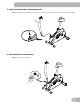
ASSEMBLY 1. Install Stabilizers to Frame Note: Make sure the Schwinn® decal on the Rear Stabilizer faces outward from the machine. 1 X4 L 13 2 3 14 X2 M 2. Attach Pedals to Frame Assembly Note: T he Left Pedal is reverse-threaded. Be sure to attach Pedals on the proper side of the Bike. Orientation is based from a seated position on the bike. The Left Pedal has an “L”, the Right Pedal an “R”.
3. Loosen and Pull the Seat Post Adjustment Knob to Attach Seat Post to Frame Assembly NOTICE: T he Adjustment Knob is pre-installed on the Main Frame. Make sure the Adjustment Knob engages the Seat Post. ! Do not set the Seat Post position higher than the stop mark (MAX) on the tube. 6 4.
5. Connect Console Mast Cable to Frame Assembly Cable NOTICE: Align the clips on the cable connectors and make sure the connectors lock. Do not crimp Console Cable. 8 6. Attach Console Mast to Frame Assembly NOTICE: Do not crimp the cables.
7. Attach Handlebars to Frame Assembly Note: P ut the T-nut (I) into the Handlebar slider and align it with the second hole (9a) to install the Console Slider Adjustment Knob (J) and washer (L). Push the Console Mast cable slightly down and push the Handlebar into the Handlebar slider until the holes are aligned to pull the cable up. NOTICE: Do not crimp the cables. Make sure that the lower Heart Rate cable (9b) is connected.
8. Attach Console Bracket to Frame Assembly NOTICE: Do not crimp the cables.
9. Install Console on Console Mast Note: R emove the pre-installed screws from the back of the Console before you connect the cables. NOTICE: Do not crimp the cables.
10. Adjust and Tighten the Console Mast and Console NOTICE: Tighten hardware and install Caps.
11. Attach Water Bottle Holder to Console Mast Note: H ardware is pre-installed on Mast and not on Hardware Card. 15 12. Connect AC Adapter to Frame Assembly 12 13. Final Inspection Inspect your machine to ensure that all hardware is tight and components are properly assembled. Be sure to record the serial number in the field provided at the front of this manual. Do not use until the machine has been fully assembled and inspected for correct performance in accordance with the Owner’s Manual.
BEFORE YOU START Moving the Bike To move the upright bike, carefully pull the Handlebars toward you while pushing the front of the bike downward. Push the bike to the desired location. NOTICE: B e careful when you move the bike. Abrupt motions can affect the computer operation. Leveling the Bike Levelers are found on each side of the Rear Stabilizer. Turn the knob to adjust the stabilizer foot. Make sure the bike is level and stable before you exercise.
Important Safety Instructions This icon means a potentially hazardous situation which, if not avoided, could result in death or serious injury. Before using this equipment, obey the following warnings: Read and understand the complete Owner's Manual. Keep the Owner's Manual for future reference. ead and understand all warnings on this machine. If at any time the Warning stickers become loose, unreadable or R dislodged, contact Nautilus® Customer Service for replacement stickers.
FEATURES A FUN RIDES CHALLENGES ROLLING HILLS UPHILL FINISH RIDE IN THE PARK CROSS-TRAINING EASY TOUR MOUNTAINS INTERVAL PIKES PEAK MOUNT HOOD PYRAMIDS QUICK START B Q START FUN RIDES MOUNTAINS CHALLENGES ENTER STOP RESET L J N M C K M O I D H E G P G F A Console J Contact Heart Rate (CHR) Sensors B Upright Handlebars K Water Bottle Holder C Adjustable Seat L Media Tray D Fully Shrouded Flywheel M MP3 / Smart Phone Holder E Levelers N Speakers F AC Adapte
Console Features The Console provides important information about your workout and lets you control the resistance levels while you exercise. The Console has a grid display with touch control buttons to navigate you through the exercise programs.
Watt / Level The WATT display field shows the power that you are producing at the current resistance level (1 horsepower = 746 watts) for 6 seconds, and then the current resistance LEVEL (1–16) for 6 seconds. Time / Interval The TIME display field shows the time count of the workout for 6 seconds, and then the current INTERVAL segment of the workout for 6 seconds. If the workout has a preset time, the time display starts at the preset value and counts down to zero.
Your at-rest heart rate is influenced by endurance training. The typical adult has an at rest heart rate of approximately 72 BPM, where as highly trained runners may have readings of 40 BPM or lower. The Heart Rate table is an estimate of what Heart Rate Zone (HRZ) is effective to burn fat and improve your cardiovascular system. Physical conditions vary, therefore your individual HRZ could be several beats higher or lower than what is shown.
OPERATIONS What to Wear Wear rubber-soled athletic shoes. You will need the appropriate clothes for exercise that allow you to move freely. How Often Should You Exercise Consult a physician before you start an exercise program. Stop exercising if you feel pain or tightness in your chest, become short of breath, or feel faint. Contact your doctor before you use the machine again. Use the values calculated or measured by the machine’s computer for reference purposes only.
Handlebar Adjustment To adjust the handlebar position: 1. Loosen the Handlebar Adjustment Knob below the Handlebar. 2. Carefully slide the handlebar forward or rearward to the desired position. Be sure not to crimp the console cables. 3. Fully tighten the knob. Power-Up Mode The Console will enter Power-Up Mode if it is plugged into a power source, any button is pushed, or if it receives a signal from the RPM sensor as a result of pedaling the machine. Note: The Console does not use batteries.
Schwinn Advantage™ User Setup Mode The Schwinn® 45 Series console lets you store and use 2 User profiles. The User profiles automatically record the workout results for each User profile, and let you view your workout data.
Edit User Profile 1. From the Power-Up Mode screen, push Schwinn Advantage™ button and hold for 3 seconds to go to User Setup Mode. To exit the User Selection option, push STOP and the console will go back to the Power-Up Mode screen. 2. The Console will show a prompt to edit the user (EDIT ) or delete the user (DELETE ). Note: I f only one User was set up, the Edit User menu includes a CREATE USER 2 option. The steps to set up User 2 are the same as the CREATE USER option.
Profile Programs These programs automate different resistances and workout levels. You can use the Program Menu to start a Profile Program or use the buttons on the console to make a quick selection. Fun Rides Rolling Hills Ride in the Park Easy Tour Mountains Pike’s Peak Mount Hood Pyramids Challenges Uphill Finish Cross-Training Interval To start a Profile Program without user setup data: 1. Sit on the machine. 2.
4. Use the Increase() and Decrease() buttons to change the resistance level (default level is 3, maximum level is 8), and push START/ENTER. 5. Push the START/ENTER button to start the Profile workout. Fitness Test The Fitness Test measures the improvements of your physical fitness level. The test compares your power output (in Watts) to your heart rate. As your fitness level improves, your power output will increase at a given heart rate.
Results / Cool Down Mode After a workout the TIME display shows 00:00 and then starts to count up. During this Cool Down period, the Console shows the Workout Results and your current Heart Rate. All workouts except Quick Start have a 3-minute Cool Down period. The LCD display shows each workout data value for 4 seconds: TIME, DISTANCE, CALORIE, AVG/MPH (KMH), AVG/ PWR, AVG/HR, MAX/HR. You can use the Increase/Decrease buttons to move through the results manually.
CONSOLE SETUP MODE Console Setup Mode The Console Setup Mode lets you set the units of measurement to either English or Metric, set the machine type, adjust the contrast of the display, or see maintenance statistics (Run Hours – for service technician use only). 1. Hold down the Increase button and Decrease button together for 3 seconds while in the Power-Up Mode to go into the Console Setup Mode. Note: Push STOP to go back to the previous screen or the Power-Up Mode screen. 2.
MAINTENANCE Maintenance Read all maintenance instructions fully before you start any repair work. In some conditions, an assistant is required to do the necessary tasks. Equipment must be regularly examined for damage and repairs. The owner is responsible to make sure that regular maintenance is done. Worn or damaged components must be repaired or replaced immediately. Only manufacturer supplied components can be used to maintain and repair the equipment.
Maintenance Parts C D A B E F EE H FF DD O CC I G J K L AA M N BB Z Y K W O X P Q R S T V U A Console L Pedal, Right W AC Adapter Plug B Console Bracket M Shroud, Right X Shroud, Left C Console Adjustment Knob N Stabilizer, Rear Y Pedal, Left D CHR Sensors O Crank Arm Z Stabilizer, Front E Handlebar P Speed Sensor AA Transport Wheel F Handlebar Adjustment Knob Q Speed Sensor Magnet BB Leveler G Seat Post R Pulley CC Console Mast H Seat S
Troubleshooting Condition/Problem No display/partial display/ unit will not turn on Things to Check Solution Check electrical (wall) outlet Make sure unit is plugged into a functioning wall outlet. Check connection at rear of unit Connection should be secure and undamaged. Replace adapter or connection at unit if either are damaged. Check data cable integrity All wires in cable should be intact. If any are visibly crimped or cut, replace cable.
Condition/Problem Console shuts off (enters sleep mode) while in use Things to Check Solution Check electrical (wall) outlet Make sure unit is plugged into a functioning wall outlet. Check connection at rear of unit Connection should be secure and undamaged. Replace adapter or connection at unit if either are damaged. Check data cable integrity All wires in the cable should be intact. If any are cut or crimped, replace cable.
WARRANTY Who Is Covered This warranty is valid only to the original purchaser and is not transferable or applicable to any other person(s). What Is Covered Nautilus, Inc. warrants that this product is free from defects in materials and workmanship, when used for the purpose intended, under normal conditions, and provided it receives proper care and maintenance as described in the Product’s Assembly and Owner’s manual.
EN Nautilus® 8000261.082412.