Do not print this page
©2006. Nautilus, Inc. All Rights Reserved. Schwinn is a registered trademark. Nautilus, Inc., World Headquarters, 16400 SE Nautilus Dr.
RECUMBENT ASSEMBLY GUIDE PN 001-6962 REV B (090706) ASSEMBLY GUIDE
CONTENTS Table of Contents Hardware ................................................................................................ 2 Exploded View ........................................................................................ 4 Parts List ................................................................................................. 5 Assembly Instructions ..........................................................................6 Important Contact Numbers ....................................
Note: Please verify you have all correct parts and quantities before assembling unit. If you are missing items, are short quantities, or have damaged components, please contact Schwinn at 1.800.864.1270 2 �� �� �� �� �� I-6 Screws M8x16mm ���� �� I-4 lock nut for M8 � (1) I-1 M8xP1.25x85mm ���� �� �� I-10 Carriage Bolt M8xP1.25x85MM (1) �� ���� ��� ��� ��� ��� ��� ��� ��� Socket Wrench���� Screwdriver�������������������� I-7 Allen Bolt M8xP1.
�� �� ������������ �������� (4) �� �� �� �� �� �� �� ��� ��� ��� ��� ��� ��� ��� ��� ��� ��� I-3 Regular Washer 8*16*2t(15) I-7 Allen Bolt M8xP1.0x45mm (4) ��� ��� ��� ��� ��� ��� ��� ���� I-5 Allen Bolt M8xP1.25x16mm (5) Allen Key���� HARDWARE Note: Please verify you have all correct parts and quantities before assembling unit. If you are missing items, are short quantities, or have damaged components, please contact Schwinn at 1.800.864.
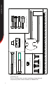
EXPLODED VIEW EXPLODED VIEW � ��� ��� ��� � ���� ��� ��� ���� ��� ��� ��� ��� � ��� ��� ��� ��� ��� ��� ��� ��� ��� ��� ��� ��� ��� � ��� ��� ��� � ��� ���� � ���� ���� ���� ���� ���� � � ��� ��� � 4 ���
PARTS LIST PARTS LIST Ref. Description Qty A A-1 A-2 B C C-1 C-2 C-3 C-4 D D-1 D-2 D-17 D-18 D-22 E F G H I-1 I-2 I-3 I-4 I-5 I-6 I-7 I-8 I-10 J K-1 K-2 K-3 L L-1 Computer Computer bracket Screw M5x14L Handlebar Handlebar mast Screw M8x1.25X16 Curved Washer Upper heart rate wire Upper Computer Wire Main frame Lower heart rate wire Lower computer wire AC Adaptor Screw M8x1.25x16L Seat rail bracket Front stabilizer Pedal pair Rear stabilizer Seat rail Screw M8xP1.
ASSEMBLY INSTRUCTIONS Basic Assembly Principles Here are a few basic tips that will aid in the assembly process . By using these principles, you can simplify each process and save yourself extra time and effort. 1. To make the assembly process go faster, gather the pieces you need for each step and thoroughly read the assembly instructions for that step prior to starting assembly for the step. 2.
ASSEMBLY INSTRUCTIONS Step 1 Install Front and Rear Stabilizers Parts: • Front Stabilizer (Ref. E ) • Rear Stabilizer (Ref. G ) • M8x16 Screws (Ref. I-6) Tools: • Supplied Allen Wrench 1-1 Attach the Rear Stabilizer (G) to the rear of the Main Unit using two M8 X 16mm screws (I-6). 1-2 Attach the Front Stabilizer (E) with the UP sticker and wheels toward the front of the Main Unit using two M8 X 16mm screws.
ASSEMBLY INSTRUCTIONS Step 2 Install Pedals Parts: • Right Pedal (F-R) • Right Pedal (F-L) Tools: • Supplied Pedal Wrench 2-1 Screw the Left Pedal ( has an “L” stamped into the end of the pedal ) into the Left Crank Arm. Note: The Left Pedal has a left handed thread and screws in counter clockwise. 2-2 Screw the Right Pedal ( has an “R “stamped into the end of the pedal ) into the Right Crank Arm.
ASSEMBLY INSTRUCTIONS Step 3 Install Handlebar Parts: • Seat Frame (Ref. L) • Handlebar (Ref. J) • Four M8x16 screws (Ref. I-5) • Four 8x16x2 Washers (Ref. I-3) Tools: • Supplied Allen Wrench 3-1 Align Handlebar with holes in Seat Frame. 3-2 Install and completely tighten the hardware.
ASSEMBLY INSTRUCTIONS Step 4 Install Seat Bottom Parts: • Seat Bottom (Ref. K-1) • Four M8x1x45 Screws (Ref. I-7) • Four 8x16x2 Washers (Ref. I-3) Tools: • Supplied Allen Wrench 4-1 Align the Seat Bottom (K-1) with the Seat Frame. 4-2 Install and completely tighten the hardware.
ASSEMBLY INSTRUCTIONS Step 5 Install Seat back Parts: • Seat Bottom (Ref. L-1) • Four M8x1x45 Screws (Ref. I-7) • Four 8x16x2 Washers (Ref. I-3) Tools: • Supplied Allen Wrench 5-1 Align the Seat Back (L-1) with the Seat Frame. 5-2 Install and completely tighten the hardware. Note: There are two sets of holes in the Seat Back. You may use the upper or lower set of holes to find the the most comfortable position.
ASSEMBLY INSTRUCTIONS Step 6 Install Bottle Holder Parts: • Water Bottle Holder (Ref. K-2) • Four M5x16 Screws (Ref. I-8) Tools: • Supplied Phillips Head Screwdriver 6-1 Align the Water Bottle Holder under the left side of the Seat Bottom. 6-2 Install and completely tighten the hardware.
Tools: • Supplied Allen Wrench 7-1 Unscrew the the seven screws and washers (D-18) that secure the Seat Rail (H) and remove the Seat Rail from the unit. (Figure A) Note: You will have to disconnect the Heart Rate Wire (M). Do not let the Heart Rate Wire fall into the frame. 7-2 Unscrew the two screws and washers (D-18) that secure the Seat Rail Bracket (D-22) and remove the bracket from the Seat Rail.
ASSEMBLY INSTRUCTIONS Step 8 Install Seat Assembly Parts: • Seat Assembly (From step 3-6) • Seat Rail (Ref. H) • Seat Rail Bracket (Ref. D-22) Tools: • Supplied Allen Wrench 8-1 Pull out on the Seat Adjustment Knob (K-3) while sliding the Seat Assembly onto the Seat Rail (H). Release the Adjustment Knob to lock the Seat Assembly in place. Note: Make sure the seat Adjustment Knob is on the side of the Seat Rail that has the holes. 8-2 Reinstall the Seat Rail Bracket.
ASSEMBLY INSTRUCTIONS Step 9 Install Handlebar Mast Parts: • Handlebar Mast (Ref C) Tools: • Supplied Allen Wrench 9-1 Remove the four Allen Bolts (C-1) and Curved Washers (C-2) from the frame . 9-2 Connect the Upper and Lower Computer Wires and Heart Rate Wires. (Detail A) 9-3 Insert the Handlebar Mast (C) into the main unit. 9-4 Re-install the four Allen Bolts and Curved Washers and completely tighten.
ASSEMBLY INSTRUCTIONS Step 10 Install Handlebar Parts: • Handlebar (Ref B) • Washer (Ref I-3) • Screw M8x16 (Ref I-5) 10-1 Tuck the Computer Wires into the Mast to allow insertion of the Handlebar . 10-2 Slide the Handlebar (B) into the Mast and secure with the Console M8x16 Screw (I-5) and Washer (I-3) . (Figure A) 10-3 Pull the Computer Wires back up through the Handlebar as shown.
ASSEMBLY INSTRUCTIONS Step 11 Install Computer Bracket Parts: • Computer Bracket (Ref. A-1) • Angle Adjust Knob (Ref. I-2) • Carriage Bolt M8x1.25x85 (Ref. I-10) • Screw M8x85 (Ref. I-1) • 2 Washers (Ref. I-3) • Hex Nut (Ref. I-4) Tools: • Supplied Socket and Flat Wrenches 11-1 Align the Computer Bracket (A-1) with the holes in the Mast. (See assembled view for reference) 11-2 Install and completely tighten the hardware.
ASSEMBLY INSTRUCTIONS Step 12 Install Computer Parts: • Computer (Ref. A ) Tools: • Supplied Phillips Head Screwdriver 12-1 Remove the four screws from the back of the Computer. 12-2 Connect the Computer Wire and Heartrate Wire to the connectors on the back of the Computer as shown. 12-3 Align the Computer with the holes in the Computer Bracket. (A-1) 12-4 Install and completely tighten the hardware.
ASSEMBLY INSTRUCTIONS Step 13 Plug in AC Adapter Parts: • AC Adapter (Ref. D-17) 13-1 Plug the AC Adapter (P) into the recepticle on the front right of the unit and into a 110 volt outlet.
ASSEMBLY INSTRUCTIONS Assembly is complete! Please reference the Owner’s Manual for information regarding computer operation, product maintenance, Warranty information, and general fitness and exercise guidelines.
If you need assistance, please have both the serial number of your machine and the date of purchase available when you contact the appropriate Nautilus office listed below. OFFICES IN THE UNITED STATES: E-mail: cstech@nautilus.com • NAUTILUS INNOVATION CENTER Nautilus, Inc. 1886 Prairie Way Louisville, Colorado, USA 80027 Phone: 800-NAUTILUS (800-6288458) Fax: 800-898-9410 • TECHNICAL/CUSTOMER SERVICE Nautilus, Inc.