230 / 430 / 470 / Manual en Español Latino Americano: http://www.schwinnfitness.
TABLE OF CONTENTS Important Safety Instructions - Assembly 3 Safety Warning Labels / Serial Number 4 Specifications 5 Before Assembly 5 Parts 6 Hardware 7 Tools 7 Assembly 8 Moving the Machine 18 Leveling the Machine 19 Important Safety Instructions 20 Features 21 Console Features 22 Operations 27 Adjustments 27 Power Up / Idle Mode 27 Quick Start Program 28 User Profiles 28 Pausing or Stopping 32 Results / Cool Down Mode 33 GOAL TRACK Statistics 33 Console Service Mode 36
IMPORTANT SAFETY INSTRUCTIONS -ASSEMBLY This icon means a potentially hazardous situation which, if not avoided, could result in death or serious injury. Obey the following warnings: Read and understand all warnings on this machine. Carefully read and understand the Assembly instructions. • Keep bystanders and children away from the product you are assembling at all times. • Do not connect power supply to the machine until instructed to do so.
SAFETY WARNING LABELS AND SERIAL NUMBER • Read, understand and obey all warnings on this machine. • Keep children away. • Not intended for use by anyone under 14 years of age. • Prior to use, read and understand the Owner’s Manual. • Injury or death is possible if Caution is not used while using this machine. • The maximum user weight for this machine is 300 lbs (136 kg). • Replace any “Caution”, “Warning” or “Danger” label that is illegible, damaged, or removed.
SPECIFICATIONS 49.9” (126.8 cm) 64” (162.5 cm) Maximum User Weight: 300 lbs. (136 kg) Power Requirements: Operational Voltage: Operational Voltage 9VDC Operating Current: 1500 mA Regulatory Approvals: AC Power Adapter: UL listed, CEC certified (or equivalent), Rated 120V 60Hz Input, 9VDC, 1500mA Output. Class 2. 27.7” (70.3 cm) This product, its packaging, and components contain chemicals known to the State of California to cause cancer, birth defects, or reproductive harm.
PARTS 17 2 1 3 5 16 6 4 14 15 7 13 8 9 12 Item Qty 1 1 2 6 Description 10 11 Item Qty Description Console 10 1 AC Adapter 1 Water Bottle Holder 11 1 Left Pedal 3 1 Seat Back 12 1 Front Stabilizer 4 1 Cover 13 1 Right Pedal 5 1 Seat Frame Assembly 14 1 Upper Shroud 6 1 Seat Bottom 15 1 Shroud Cap 7 1 Seat Adjustment Handle 16 1 Console Mast 8 1 Rear Stabilizer 17 1 MP3 Cord 9 1 Frame
HARDWARE / TOOLS A Item Qty A 8 B B C D Description E F G H I J Description Item Qty Button Head Hex Screw, M8x20 F 2 Phillips Head Screw, M5x12 10 Button Head Hex Screw, M6x12 G 14 Lock Washer, M6 C 4 Flat Washer, M8 H 4 Curved Washer, M6 D 8 Lock Washer, M8 I 4 Phillips Head Screw, M6x25 E 10 Flat Washer, M6 J 4 Curved Washer, M8 Tools Included Not Included (recommended) 4 mm 6 mm 7
ASSEMBLY 1. Attach Stabilizers to Frame Note: H ardware is pre-installed and not on the Hardware Card.
2. Attach the Seat Frame Assembly to the Seat Rail NOTICE: Do not crimp the Heart Rate Cable. Once all hardware has been inserted, be sure to fully tighten it.
3.
4.
5.
6. Connect the Cables and Attach the Console Mast to Frame Assembly NOTICE: Do not crimp Console Cables.
7. Remove Hardware from Console NOTICE: Do not crimp the cable. Note: H ardware is pre-installed and not on the Hardware Card. * 1 X4 * #2 8. Connect Cables and Attach Console to Frame Assembly NOTICE: Align the clips on the cable connectors and make sure the connectors lock. Do not crimp cables.
9. Attach Pedals to Frame Assembly NOTICE: The Left Pedal is reverse-threaded. Be sure to attach Pedals on the proper side of the Bike. Orientation is based from a seated position on the bike. The Left Pedal has an “L”, the Right Pedal an “R”.
10.
11. Connect AC Adapter to Frame Assembly 10 12. Final Inspection Inspect your machine to ensure that all hardware is tight and components are properly assembled. Be sure to record the serial number in the field provided at the front of this manual. Do not use until the machine has been fully assembled and inspected for correct performance in accordance with the Owner’s Manual.
BEFORE YOU START Moving the Bike The machine may be moved by one or more persons depending on their physical abilities and capacities. Make sure that you and others are all physically fit and able to move the machine safely. 1. Remove the power cord. 2. Use the Transport Handle to carefully lift the machine onto the transport rollers. 3. Push the machine into position. 4. Carefully lower the machine into position. NOTICE: B e careful when you move the bike.
Leveling the Bike Levelers are found on each side of the Rear Stabilizer and on the Frame Rail. On the Rear Stabilizer, turn the knob to adjust the stabilizer foot. To adjust the leveler on the Frame Rail: 1. Loosen the upper locking nut. 2. Turn the leveler to adjust the height. Do not adjust the levelers to such a height that they detach or unscrew from the machine. Injury to you or damage to the machine can occur. 3. Tighten the upper locking nut to lock the leveler.
IMPORTANT SAFETY INSTRUCTIONS This icon means a potentially hazardous situation which, if not avoided, could result in death or serious injury. Before using this equipment, obey the following warnings: Read and understand the complete Manual. Keep the Manual for future reference. ead and understand all warnings on this machine. If at any time the Warning stickers become loose, unreadable or R dislodged, contact Nautilus Customer Service for replacement stickers.
FEATURES B C D A S O N P F Q E R M L G K H J K J I A Console K Leveler B MP3 Input L Transport Handle C USB Port M Seat Adjustment Knob D Media Tray N Water Bottle Holder E Fan O Adjustable Seat F Speakers P Contact Heart Rate (CHR) Sensors G Fully Shrouded Flywheel Q Handlebar, Side H Power Connector R Pedal I Transport Wheel S Handlebar, Upright J Stabilizer 21
Console Features The Console provides important information about your workout and lets you control the resistance levels while you exercise. The Console features the Schwinn Dual Track™ display with touch control buttons to navigate you through the exercise programs.
Resistance Level Quick Buttons- Shifts the resistance levels to the setting quickly during a workout Achievement Indicator Lights- when a workout result is reviewed, the achievement indicator light will activate. Schwinn Dual Track™ Display Upper Display Data 10 9 8 7 6 5 4 3 2 1 10% 40% 70% User Display Achievement Display Program Display The Program Display shows information to the User and the grid display area shows the course profile for the program.
10% 40% 70% Lower Display Data Hr USE/ ND 20 GOAL TRACK 16 The Lower Display shows the Workout Values. and can be customized for each User (Consult the “Edit User Profile” section of this manual). 12 CURRENT WORKOUT Speed LAST WORKOUT LAST 7 DAYS 7 The Speed display field shows the machine speed in miles per hour (mph) or kilometers per hour (km/h).
Contact Heart Rate Sensors Contact Heart Rate (CHR) sensors send your heart rate signals to the Console. The CHR sensors are the stainless steel parts of the Handlebars. To use, put your hands comfortably around the sensors. Be sure that your hands touch both the top and the bottom of the sensors. Hold firm, but not too tight or loose. Both hands must make contact with the sensors for the Console to detect a pulse. After the Console detects four stable pulse signals, your initial pulse rate will be shown.
The graph is a brief guideline, describing the generally suggested target heart rates based on age. As noted above, your optimal target rate may be higher or lower. Consult your physician for your individual target heart rate zone. Note: A s with all exercises and fitness regimens, always use your best judgment when you increase your exercise time or intensity.
OPERATIONS What to Wear Wear rubber-soled athletic shoes. You will need the appropriate clothes for exercise that allow you to move freely. How Often Should You Exercise Consult a physician before you start an exercise program. Stop exercising if you feel pain or tightness in your chest, become short of breath, or feel faint. Contact your doctor before you use the machine again. Use the values calculated or measured by the machine’s computer for reference purposes only.
Initial Setup During the first power-up, the Console should be setup with the date, time and your preferred measurement units. 1. Date: Push the Increase/Decrease buttons to adjust the currently active value (flashing). Push the Left/Right buttons to change which segment is the currently active value (month / day / year). 2. Push OK to set. 3. Time: Push the Increase/Decrease buttons to adjust the currently active value (flashing).
Select a User Profile Every workout is saved to a User Profile. Be sure to select the proper User Profile before starting a workout. The last User that completed a workout will be the default user. User Profiles are assigned the default values until they are customized by editing. Be sure to edit the User Profile for more accurate calorie and heart rate information. From the Power-Up Mode screen, push the Increase() or Decrease() buttons to select one of the User Profiles.
Hr 9. The Console will go to the Power-Up Mode screen with the user selected. Reset a User Profile 1. From the Power-Up Mode screen, push the Increase() or Decrease() buttons to select one of the User Profiles. 2. Push the OK button to select the User Profile. 3. The Console display shows the current User Profile name and the EDIT prompt. Push the Increase() or Decrease() buttons to change the prompt.
Rolling Hills Ride in the Park Easy Tour Easy Tour Stream Crossing Ride in the Park Stream Crossing Ride in the Park Easy Tour Easy Tour Stream Crossing Pike’s Peak Pike’s Peak Mount Hood Mount Hood Pike’s Peak Mount Hood Pyramids Pyramids Summit Pass FUN RIDES Ride in the Park FUN RIDES Rolling Hills MOUNTAINS Easy Tour Stream Crossing Pike’s Peak Mount Hood Mount Hood Pyramids Pyramids Summit Pass Uphill Finish Cross-Training Cross-Training Interval Interval Stai
You can start the Fitness Test from the FEEDBACK category. The Fitness Test program first prompts you to select your fitness level—Beginner ( “BEG” ) or Advanced ( “ADV” ). The Console will use the Age and Weight values for the selected User Profile to calculate the Fitness Score. Start to workout and hold the Heart Rate Sensors. When the test starts, the intensity of the workout slowly increases. This means you will work harder, and as a result, your heart rate increases.
Pausing or Stopping The Console will go into Pause Mode if the user stops pedaling and pushes PAUSE/END during a workout, or there is no RPM signal for 5 seconds (user not pedaling). The Console will cycle through a series of messages that change every 4 seconds: - WORKOUT PAUSED - PEDAL TO CONTINUE (if a bike) / STRIDE TO CONTINUE (if an elliptical) - PUSH END TO STOP During a paused workout, you can use the Increase/Decrease buttons to move through the result channels manually. 1.
2. Push the GOAL TRACK button. The Console will display the LAST WORKOUT values and activate the corresponding Achievement light. Note: G oal Track statistics can be viewed even during a workout. Push GOAL TRACK and the LAST WORKOUT values will be displayed. The workout values for the current workout will be hidden except for the GOAL display. Push GOAL TRACK again to return to the Power-Up screen. 3. Push the Increase() button to move to the next GOAL TRACK statistic, “LAST 7 DAYS”.
CONSOLE SETUP MODE The Console Setup Mode lets you input the date and time, set the units of measurement to either English or Metric, change the machine type, control the sound settings ( on/ off), or see maintenance statistics (Error Log and Run Hours – for service technician use only). 1. Hold down the PAUSE/END button and Right button together for 3 seconds while in the Power-Up Mode to go into the Console Setup Mode.
MAINTENANCE Read all maintenance instructions fully before you start any repair work. In some conditions, an assistant is required to do the necessary tasks. Equipment must be regularly examined for damage and repairs. The owner is responsible to make sure that regular maintenance is done. Worn or damaged components must be repaired or replaced immediately. Only manufacturer supplied components can be used to maintain and repair the equipment.
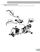
Maintenance Parts A B CC C D AA BB Z Y E F G X H W K N V M O P L J I T U Q S R 37
A Console K Frame Assembly U Flywheel B Seat Back L Transport Wheel V Console Cable, Lower C Seat Cover M Stabilizer, Front W Shroud, Right D Water Bottle Holder N Heart Rate Cable, Lower X Pedal, Right E Handlebar, Side O Speed Sensor Magnet Y Shroud, Upper F Seat Bottom P Speed Sensor Z Shroud Cap G Seat Adjustment Handle Q Crank Arm AA Console Cable, Upper H Rear Stabilizer R Servo Motor BB Heart Rate Cable, Lower I Shroud, Left S Brake Assembly CC Con
TROUBLESHOOTING Condition/Problem No display/partial display/ unit will not turn on Things to Check Solution Check electrical (wall) outlet Make sure unit is plugged into a functioning wall outlet. Check connection at front of unit Connection should be secure and undamaged. Replace adapter or connection at unit if either are damaged. Check data cable integrity All wires in cable should be intact. If any are visibly crimped or cut, replace cable.
No speed/RPM reading, Console displays “Please Pedal” error code Check data cable integrity All wires in cable should be intact. If any are cut or crimped, replace cable. Check data cable connections/orientation Be sure cable is connected securely and oriented properly. Small latch on connector should line up and snap into place. Check magnet position (requires shroud removal) Magnet should be in place on pulley.
WARRANTY Who Is Covered This warranty is valid only to the original purchaser and is not transferable or applicable to any other person(s). What Is Covered Nautilus, Inc. warrants that this product is free from defects in materials and workmanship, when used for the purpose intended, under normal conditions, and provided it receives proper care and maintenance as described in the Product’s Assembly and Owner’s manual.
EN Nautilus® 8002152.100114.