Do not print this page
©2006. Nautilus, Inc. All Rights Reserved. Schwinn is a registered trademark. Nautilus, Inc., World Headquarters, 16400 SE Nautilus Dr.
elliptical Assembly guide 001-6986-070709C Assembly Guide
CONTENTS Table of Contents Hardware ................................................................................................ 2 Exploded View......................................................................................... 4 Parts List . ................................................................................................ 5 Assembly Instructions .......................................................................... 6 Important Contact Numbers ..................................
M8 WASHER REGULAR (36) M8 WAVE WASHER (2) M8 WASHER WIDE (4) M8 x 15L BUTTON HEAD (32) M8 x 20L BUTTON HEAD (4) M8 x 20L HEX HEAD THREAD LOCK (4) M5 x 10L PHILLIPS HEAD (4) Hardware Note: Please verify you have all correct parts and quantities before assembling unit. If you are missing items, are short quantities, or have damaged components, please contact Schwinn at 1.800.864.
M8 WASHER LOCKING (40) COMBO WRENCH (2) STAPLED TO THE HARDWARE CARD COTTER PIN (2) M5 x 20L PHILLIPS HEAD (2) ALLEN WRENCH (1) END CAPS (4) M8 x 25L FLAT HEAD THREAD LOCK (6) REGULAR (36) HARDWARE Note: Please verify you have all correct parts and quantities before assembling unit. If you are missing items, are short quantities, or have damaged components, please contact Schwinn at 1.800.864.
Exploded View EXPLODED VIEW U P D F K J O L V Q A T B R C M T J S H W G E 4 I
PARTS LIST PARTS LIST Ref.
ASSEMBLY INSTRUCTIONS Basic Assembly Principles Here are a few basic tips that will aid in the assembly process . By using these principles, you can simplify each process and save yourself extra time and effort. 1. To make the assembly process go faster, gather the pieces you need for each step and thoroughly read the assembly instructions for that step prior to starting assembly for the step. 2.
ASSEMBLY INSTRUCTIONS Step 1 Install Rear Stabilizer and Extrusion Handlebar Parts: • Two Extrusion Assemblies (Ref. H) • Rear Stabilizer (Ref. G ) • Extrusion Handlebar Assembly (Ref. I) Tools: • Supplied Allen Wrench 1-1 Attach, but do not tighten, the Extrusion Assemblies (Ref H) to the Rear Stabilizer Assembly (Ref G) using twelve M8x15L button head (Ref 1) twelve M8 washers locking (Ref 5) and twelve M8 washers regular (Ref 3).
ASSEMBLY INSTRUCTIONS Step 2 Install front stabilizer and Extrusion Assembly Parts: • Front Stabilizer (Ref E) • Extrusion Assembly (From step 1) • Main Unit (Ref A) Tools: • Supplied Allen Wrench 2-1 Attach the Front Stabilizer (Ref E) to the Main Unit (Ref A) using two M8x25 flat head screws (Ref 2) and completely tighten the hardware.
ASSEMBLY INSTRUCTIONS Step 3 Install Console Mast Parts: • Console Mast (Ref K) • Main Unit Tools: • Supplied Allen Wrench 3-1 Connect the wire harness from the Main Unit to the wire harness in the Console Mast. 3-2 Slide the Console Mast (Ref K) down onto the Main Unit and secure using six M8x15L button head (Ref 1), six M8 washers regular (Ref 3) and six M8 washers locking (Ref 5).
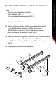
ASSEMBLY INSTRUCTIONS Step 4 Install Console Handlebar Parts: • Console Handlebar (Ref D) Tools: • Supplied Phillips Head Screwdriver 4-1 Feed the Wire Harness (Ref W1) from the Mast (Ref K) and the Contact Heart Rate Wire (Ref W2) from the Console Handlebar through the hole in the Console Handlebar (Ref D). 4-2 Secure the Console Handlebar to the Mast using four M5x10L phillps screws (Ref 8).
Parts: • Console (Ref U) Tools: • Supplied Phillips Head Screwdriver NOTE: Before installing the console, make sure the toggle switch on the back of the Console (beside wire connectors) is set to EP. 5-1 Remove the four M5x10 phillps screws (Ref 9) from the back of the console. 5-2 Connect the Wire Harness (Ref W1) and Contact Heart Rate Wire (Ref W2) to the back of the Console.
ASSEMBLY INSTRUCTIONS Step 6 Install Right and Left leg Parts: • Right Leg (Ref R) • Left Leg (Ref S) Tools: • Supplied Combo Wrench 6-1 Attach the Right leg (Ref S), marked with an “R” sticker that can be removed, to the post on the Crank (Ref C1) using one M8x20L hex head thread lock (Ref 10) one M8 washer locking (Ref 5) and one M8 washer wide (Ref 4). 6-2 Repeat the procedure for the Left Leg (Ref R) marked with an “L” sticker that can be removed.
ASSEMBLY INSTRUCTIONS Step 7 Install Right and Left Lower Handlebars Parts: • Arm Pivot Rod (Ref L) • Right Lower Handlebar (Ref Q) • Left Lower Handlebar (Ref M) Tools: • 2 Supplied Combo Wrenches 7-1 Slide the Arm Pivot Rod (Ref L) through the Console Mast (Ref K).
ASSEMBLY INSTRUCTIONS Step 8 Install Right and Left Foot Assembly Parts: • Foot Mount Plate Qty.2 (Ref T) • Right Foot Assembly (Ref C) • Left Foot Assembly (Ref B) • Arm Cotter Pin (Ref N) Tools: • Supplied Allen Wrench 8-1 Slide the shaft under the Left Foot Assembly into the Pivot (Ref P1) on the Left Leg Assembly.
ASSEMBLY INSTRUCTIONS Step 9 Install Upper Handlebars Parts: • Right Upper Handlebar (Ref P) • Left Upper Handlebar (Ref O) Tools: • Supplied Allen Wrench 9-1 Slide the Upper Left Handlebar (Ref O) into the Lower Left Handlebar and secure using four M8x15l button head (Ref 1) four M8 washers regular (Ref 3) and four M8 washers locking (ref 5). 9-1 Repeat the procedure for the Upper Right Handlebar (Ref P).
ASSEMBLY INSTRUCTIONS Step 10 Install Water Bottle Holder and AC Adapter Parts: • Water Bottle Holder (Ref F) • AC Adapter (Ref W) Tools: • Supplied Phillips Screwdriver 10-1 Align the Water Bottle Holder components (Ref F) with the Mast as shown and secure using two M5x20 phillips head (Ref 7). 10-2 Connect the AC Adapter (Ref W) to the unit as shown.
ASSEMBLY INSTRUCTIONS Assembly is complete! Please reference the Owner’s Manual for information regarding computer operation, product maintenance, warranty information, and general fitness and exercise guidelines.
IMPORTANT CONTACT NUMBERS IMPORTANT CONTACT NUMBERS If you need assistance, please have both the serial number of your machine and the date of purchase available when you contact the appropriate Nautilus office listed below. OFFICES IN THE UNITED STATES: E-mail: cstech@nautilus.com • NAUTILUS INNOVATION CENTER Nautilus, Inc. 1886 Prairie Way Louisville, Colorado, USA 80027 Phone: 800-NAUTILUS (800-6288458) Fax: 800-898-9410 • TECHNICAL/CUSTOMER SERVICE Nautilus, Inc.