30 / 1.0 170 / 1.5 Manual en Español Latino Americano: http://www.schwinnfitness.
TABLE OF CONTENTS Important Safety Instructions - Assembly 3 Safety Warning Labels / Serial Number 4 Specifications 4 Before Assembly 5 Parts 6 Hardware 7 Tools 7 Assembly 8 Leveling the Bike 14 Moving the Bike 14 Important Safety Instructions - Owner’s 15 Features 16 Console Features 17 Contact Heart Rate (CHR) 20 Operations 22 Adjustments 22 Initial Setup 22 Quick Start / Manual Program 23 User Profiles 23 Profile Programs 25 Pausing or Stopping 27 Results 27 GOAL TRACK
IMPORTANT SAFETY INSTRUCTIONS — ASSEMBLY ! This icon means a potentially hazardous situation which, if not avoided, could result in death or serious injury. Obey the following warnings: ! Read and understand all warnings on this machine. Carefully read and understand the Assembly instructions. • Keep bystanders and children away from the product you are assembling at all times. • Do not connect power supply to the machine until instructed to do so.
SAFETY WARNING LABELS AND SERIAL NUMBER Serial number Product specification • Read, understand and obey all warnings on this machine. • Keep children away. • Not intended for use by anyone under 14 years of age. • Prior to use, read and understand the Owner’s Manual. • Injury or death is possible if Caution is not used while using this machine. • The maximum user weight for this machine is 300 lbs (136 kg). • Replace any “Caution”, “Warning” or “Danger” label that is illegible, damaged, or removed.
SPECIFICATIONS Maximum User Weight: 300 lbs. (136 kg) Power Requirements: Operational Voltage: 9VDC Operating Current: 1.5A Regulatory Approvals: ISO 20957 AC Power Adapter: UL listed, Rated 120V 60Hz Input, 9VDC, 1500mA Output. Class 2. ! his product, its packaging, and components contain T chemicals known to the State of California to cause cancer, birth defects, or reproductive harm. This Notice is provided in accordance with California’s Proposition 65.
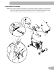
PARTS 7 8 6 16 11 14 5 9 4 15 1 10 13 (R) 2 3 12 (L) Item Qty Description Item Qty Description 1 1 Main Frame 9 1 Seat Post 2 1 Front Stabilizer 10 1 Adjustment Knob 3 1 Rear Stabilizer 11 1 Seat 4 1 Top Shroud 12 1 Left Pedal (L) 5 1 Mast Gasket 13 1 Right Pedal (R) 6 1 Console Mast (with Handlebar Mount) 14 1 Water Bottle Holder 6 7 1 Handlebars 15 1 AC Adapter 8 1 Console 16 1 Handlebar Mount Cover Note: M edia Cable is in a bag.
HARDWARE / TOOLS D Item Qty A 4 Button Head Hex Screw M8 x 25 B 5 Lock Washer M8 C 4 Curved Washer M8 D 1 Flat Washer M8 E 1 T-handle E Description Tools Included Not Included 6 mm (recommended) 7
ASSEMBLY 1. Attach Stabilizers to Main Frame Note: H ardware(*) is pre-installed on the stabilizers and not on Hardware Card. Make sure transport wheels on the front stabilizer point forward, and the Schwinn® decal on the rear stabilizer faces outward from the machine. 6 mm 6 mm X2 * * * * X2 * * 2. Install Console Mast, Mast Gasket and Top Shroud on Main Assembly NOTICE: M ake sure the Console Cable connector (a) does not fall into the Console Mast.
3. Install Handlebars on Console Mast NOTICE: D o not crimp the cables. Put the Handlebar (7) in the bracket (6a), adjust the Handlebar to the desired angle, and install the T-handle (E) through the holes. Use the pull cable in the Handlebar Mount to route the HR cable (7a) through the slot (6c) under the Handlebar Mount to the top of the mast. Fully tighten the T-handle to keep the Handlebar in position. Push the cover (16) into position on the Handlebar Mount.
4. Install Console on Console Mast Note: Remove the pre-installed screws(*) from the back of the Console before you connect the cables. NOTICE: D o not crimp the cables.
5. Install Seat Post on Frame NOTICE: M ake sure the Adjustment Knob engages the Seat Post. Do not set the Seat Post position higher than the stop mark (STOP) on the tube. 9 10 STOP 10 6. Attach Seat to Seat Post NOTICE: B e sure the Seat is straight. Tighten the nuts (11b) on the Seat bracket (11a) to hold the Seat in position.
7. Install Pedals Note: T he Left Pedal is reverse-threaded. Be sure to attach Pedals on the proper side of the Bike. Orientation is based from a seated position on the bike. The Left Pedal has an “L”, the Right Pedal an “R”.
8. Install Water Bottle Holder Note: T he hardware(*) is pre-installed on the Console Mast and not on Hardware Card. 14 X2 * 9. Connect AC Adapter 15 10. Final Inspection Inspect your machine to ensure that all hardware is tight and components are properly assembled. Be sure to record the serial number in the field provided at the front of this manual.
BEFORE YOU START Leveling Your Bike Levelers are found on each side of the Rear Stabilizer. Turn the knob to adjust the stabilizer foot. Make sure the bike is level and stable before you exercise. Moving Your Bike To move the upright bike, carefully tilt the Handlebars toward you while pushing the front of the bike downward. Push the bike to the desired location. NOTICE: B e careful when you move the bike. Abrupt motions can affect the computer operation.
IMPORTANT SAFETY INSTRUCTIONS ! This icon means a potentially hazardous situation which, if not avoided, could result in death or serious injury. Before using this equipment, obey the following warnings: ! Read and understand the complete Manual. Keep the Manual for future reference. ead and understand all warnings on this machine. If at any time the Warning stickers become loose, unreadable R or dislodged, contact Nautilus Customer Service for replacement stickers.
FEATURES A C P B Q A O M N L B K D E F R J G I H F 16 A Console J Power Connector B Handlebars K Water Bottle Holder C Adjustable Seat L MP3 Input D Adjustment Knob M USB Port E Pedals N Contact Heart Rate (CHR) Sensors F Stabilizers O Speakers G Levelers P Fan H Fully Shrouded Flywheel Q Media Tray I Transport Rollers R Media Cable
Console Features The Console provides important information about your workout and lets you control the resistance levels while you exercise. The Console features the Schwinn Dual Track™ display with touch control buttons to navigate you through the exercise programs.
0 FAN button- Controls 3-speed fan Resistance Level Quick Buttons- Shifts the resistance levels to the setting quickly during a workout Achievement Indicator Lights- when a workout result is reviewed, the achievement indicator light will activate.
8 7 6 5 4 3 2 1 Achievement Display 10% is The Achievement Display activates when a workout goal reached 40% 70% or a workout milestone is surpassed from past workouts. The Console display will congratulate and inform the User of their achievement, along with a celebratory sound. Lower Display Data Hr 20 16 12 7 The Lower Display shows the Workout Values and can be customized for each User. (Consult the “Edit User Profile” section of this manual.
Contact Heart Rate Sensors Contact Heart Rate (CHR) sensors send your heart rate signals to the Console. The CHR sensors are the stainless steel parts of the Handlebars. To use, put your hands comfortably around the sensors. Be sure that your hands touch both the top and the bottom of the sensors. Hold firm, but not too tight or loose. Both hands must make contact with the sensors for the Console to detect a pulse. After the Console detects four stable pulse signals, your initial pulse rate will be shown.
The graph is a brief guideline, describing the generally suggested target heart rates based on age. As noted above, your optimal target rate may be higher or lower. Consult your physician for your individual target heart rate zone. Note: As with all exercises and fitness regimens, always use your best judgment when you increase your exercise time or intensity.
OPERATIONS What to Wear Wear rubber-soled athletic shoes. You will need the appropriate clothes for exercise that allow you to move freely. How Often Should You Exercise Consult a physician before you start an exercise program. Stop exercising if you feel pain or tightness in your chest, become short of breath, or feel faint. Contact your doctor before you use the machine again. Use the values calculated or measured by the machine’s computer for reference purposes only.
4. Push OK to set. 5. Units of Measurement: Push the Increase/Decrease buttons to adjust between “MILES” (Imperial English) or “KM” (metric). 6. Push OK to set. The Console goes back to the Power-Up / Idle Mode screen. Note: To adjust these selections, consult the “Console Set-Up Mode” section. Quick Start ( Manual ) Program The Quick Start ( Manual ) program lets you start a workout without entering any information. During a Manual Workout, each column represents a 2 minute time period.
Edit User Profile 1. From the Power-Up Mode screen, push the Increase() or Decrease() buttons to select one of the User Profiles. 2. Push the OK button to select the User Profile. 3. The Console display shows the EDIT prompt and the current User Profile name. Push OK to start the Edit User Profile option. To exit the Edit User Profile option, push the PAUSE/END button and the console will go back to the Power-Up Mode screen. 4.
6. Push OK to make your selection. 7. The Console will go to the Power-Up Mode screen. Changing Resistance Levels Push the Resistance Level Increase() or Decrease() buttons to change the resistance level at any time in a workout program. To rapidly change the resistance level, push the desired Resistance Level Quick Button. The Console will adjust to the selected resistance level of the quick button. Profile Programs These programs automate different resistance and workout levels.
Workout Profile and Goal Program The Console lets you select the Profile Program and type of Goal for your workout (Distance, Time or Calories), and set the Goal value. 1. Sit on the machine. 2. Push the Increase() or Decrease() buttons to select the correct User profile. 3. Push the Programs button. 4. Push the Left() or Right() buttons to select a Category of Workout. 5. Push the Increase() or Decrease() buttons to select a Profile Workout, and push OK. 6.
3. Push the Increase() or Decrease() buttons to select the Goal type, and push OK. 4. Push the Increase() or Decrease() buttons to set the goal value for the workout. Note: Be sure to allow time for your heart rate to reach the desired heart rate zone when setting the goal. 5. Push OK to start the workout. Changing a Workout Program During a Workout The Console allows a different Workout Program to be started from an active workout. 1. From an active workout, push PROGRAMS. 2.
GOAL TRACK Statistics (and Achievements) The statistics from every workout are recorded to a User Profile. The Schwinn Dual Track™ Console shows the Goal Track workout Statistics on the Lower Display in three channels: a.) TIME (total), DISTANCE (total), and CALORIES (total) b.) SPEED (average), RPM (average), and HEART RATE (average) c.) TIME (average), DISTANCE (average) / or LEVEL (average) *, and CALORIES (average) * If the Goal Track Statistic is a single workout, LEVEL (average) is displayed.
6. Push the Increase() button to move to the “CLEAR WORKOUT DATA -OK?”. Push OK, and the “ARE YOU SURE? - NO” prompt will display. Push the Increase() button to change to the “ARE YOU SURE? - YES” display, and push OK. The user workouts have been reset. 7. Push GOAL TRACK to return to the Power-Up screen. www.SchwinnConnect.com Go to the www.SchwinnConnect.com web site to create an online profile, upload your workout results using a USB Flash Drive, and then view and track your achievements over time.
CONSOLE SETUP MODE The Console Setup Mode lets you input the date and time, set the units of measurement to either English or Metric, change the machine type, control the sound settings ( on/ off), or see maintenance statistics (Error Log and Run Hours – for service technician use only). 1. Hold down the PAUSE/END button and Right button together for 3 seconds while in the Power-Up Mode to go into the Console Setup Mode.
MAINTENANCE Read all maintenance instructions fully before you start any repair work. In some conditions, an assistant is necessary to do the necessary tasks. ! Equipment must be regularly examined for damage and repairs. The owner is responsible to make sure that regular maintenance is done. Worn, damaged or loose components must be repaired or replaced immediately. Only manufacWA RNING turer supplied components can be used to maintain and repair the equipment.
Maintenance Parts A K A DD J EE M L BB R C N CC Y AA B J G O H P I D Q Z X W S T D J U E C V F 32 A Console L HR Cables W Flywheel B Console Mast M CHR Sensors X Brake Assembly C Pedals N Seat Y RPM Sensor D Crank Arms O Seat Post w/ Slider Z Speed Sensor Magnet E Left Shroud P Adjustment Knob AA Servo Motor F Power Inlet Q Seat Post Shroud BB Drive Belt G Right Shroud R Water Bottle Holder CC Drive Pulley H Top Shroud S Rear Stabilizer DD
TROUBLESHOOTING Condition/Problem No display/partial display/ unit will not turn on Things to Check Solution Check electrical (wall) outlet Make sure unit is plugged into a functioning wall outlet. Check connection on console Connection should be secure and undamaged. Replace adapter or connection at unit if either are damaged. Check data cable integrity All wires in cable should be intact. If any are visibly crimped or cut, replace cable.
Condition/Problem Things to Check Solution Check data cable connections/orientation Be sure cable is connected securely and oriented properly. Small latch on connector should line up and snap into place. Reset Machine Unplug unit from electrical outlet for 3 minutes. Reconnect to outlet. Check magnet position (requires shroud removal) Magnet should be in place on pulley. Check Speed Sensor (requires shroud removal) Speed sensor should be aligned with magnet and connected to data cable.
WARRANTY Who Is Covered This warranty is valid only to the original purchaser and is not transferable or applicable to any other person(s). What Is Covered Nautilus, Inc. warrants that this product is free from defects in materials and workmanship, when used for the purpose intended, under normal conditions, and provided it receives proper care and maintenance as described in the Product’s Assembly and Owner’s manual.
SEARS CUSTOMER WARRANTY Who Is Covered This warranty is valid only to the original purchaser and is not transferable or applicable to any other person(s). What Is Covered Sears, Roebuck and Co. warrants that this product is free from defects in materials and workmanship, when used for the purpose intended, under normal conditions, and provided it receives proper care and maintenance as described in the Product’s Assembly and Owner’s manual.
EN Nautilus® 8002150.100114.