™ r Sc hwi nn®MPowe Cons ol eV2+Po we r
Specifications MPower Console V2 Speed Sensor Power Requirements Power Sensor 5.25” (13.34 cm) 2.38” (6.
Important Safety Instructions ,QGLFDWHV D SRWHQWLDOO\ KD]DUGRXV VLWXDWLRQ ZKLFK LI QRW DYRLGHG FRXOG UHVXOW LQ GHDWK RU VHULRXV LQMXU\ Before using this equipment, obey the following warnings: Read and understand the complete Owner’s Manual. Keep Owner’s Manual for future reference.
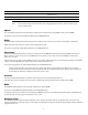
A1 A2 A3 A7 A6 A5 A4 5
A1 KM / MPH (Speed) A5 STAGE Time and Distance A2 WATTS (Power) A6 RPM (Cadence) A3 KCAL (Calories) A7 Heart Rate A4 TOTAL Time and Distance Note: If you need to change the measurement units to English Imperial or metric, refer to the User Setup section of this manual. 6SHHG The Speed display field shows the estimated speed of the bike in kilometers per hour (KM/H) or miles per hour (MPH). To view the average speed during Workout Mode, tap the AVG/END button.
Workout Totals 7KH 727$/ GLVSOD\ ILHOG VKRZV WKH WRWDO WLPH DQG GLVWDQFH UHVXOWV DW WKH HQG RI WKH ZRUNRXW 7KH 7RWDO LFRQ LV OLW GXULQJ :RUNRXW 0RGH LCD + and – Icons 7KH DQG ± SOXV DQG PLQXV LFRQV RQ WKH /&' IODVK WR SURPSW WKH XVHU WR HQWHU WKHLU ZHLJKW GXULQJ 8VHU 6HWXS 0RGH 7KH LFRQV WXUQ RII ZKHQ QRW LQ XVH Keypad 7KH PXOWL IXQFWLRQ NH\SDG OHWV \RX VHW WKH FRQVROH PHDVXUHPHQWV IRU \RXU ZRUNRXW VHH DQG XSGDWH \RXU ZRUNRXW GDWD DQG H[DPLQH WKH FRQVROH GLDJQRVWLF PHVVDJHV 7DS DQ\ EXWWRQ WR D
Errors Error messages tell you when there is a problem in the bike's operation: 8
When the Cadence decreases to less than 5 RPM for 3 seconds or more, the console pauses and the LCD Display shows the last workout data values. If you stay paused for more than 5 minutes, the workout stops and the console goes to Display Results mode. To set the STAGE time and STAGE distance back to zero for a new stage in the workout, tap the STAGE button. The TOTAL time and TOTAL distance continue the total measurement for the workout. To end the workout, push the AVG/END button and hold for 3 seconds.
Ant+ Watch HRM )RU ELNHV WKDW GR QRW KDYH D 3RZHU 6HQVRU LQVWDOOHG XVHU ZHLJKW GDWD LV QHFHVVDU\ WR FDOFXODWH WKH &DORULHV GXULQJ WKH ZRUNRXW ,I WKH FRQVROH GRHV QRW JHW WKH ZHLJKW GDWD IURP D GHYLFH \RX PXVW PDQXDOO\ VHW WKH ZHLJKW YDOXH 7KH DQG ± LFRQV RQ WKH /&' IODVK DQG WKH 530 ILHOG GLVSOD\V OEV NJ 8VH WKH 67$*( ± DQG $9* (1' EXWWRQV WR DGMXVW WKH QXPEHU WR \RXU ZHLJKW Note: 7R FKDQJH WKH ZHLJKW XQLWV WR (QJOLVK ,PSHULDO RU PHWULF 3XVK WKH 67$*( DQG $9* (1' EXWWRQV IRU VH
Display Results Device Pairing 2. Push the STAGE and AVG/END buttons for 5 seconds to go to Service Mode. 3. Tap the AVG/END button until you see the Power menu option, and push the Backlight button. 4. Push the STAGE or AVG/END button to see the Power submenu options—Sport (not power enabled) and Perform (power enabled). • If you have a Power Sensor, go to the Perform option and push the Backlight button to set.
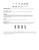
A43 A48 A44 A47 A45 A46 A43 Pairing A47 Countdown Timer (Power Sensor) A44 Countdown Timer (Speed Sensor) A48 Pairing Indicator A45 Process Status (Speed Sensor) A46 Process Status (Power Sensor) 9. The Process Status indicator(s) on the console display shows “– – –” while the Pairing operation continues. If Pairing is completed satisfactorily, the console display shows PASS. The circuit board inside the Power Sensor cover has 2 color LEDs — 1 green and 1 red.
When you select the submenu option for a specific battery (AP1, AP2, or AP3), the console shows the level of that battery. Battery Status Icon Console Speed Sensor Power Sensor Voltage 4 segments 80–100% 80–100% 1.5V or more 3 segments 60–80% 60–80% 1.3–1.499V 2 segments 40–60% 40–60% 1.1–1.299V 1 segment 20–40% 20–40% 0.9–1.099V 1 segment flashing less than 20% less than 20% less than 0.9V If the battery level is low, refer to the instructions for battery replacement in this manual.
Error History $OORZV UHYLHZ RI HUURU ORJ A1 A2 A3 A1 A2 Error Message Error Count A3 Error Sequence If the battery level is low, refer to the instructions for battery replacement in this manual.
Backlight Allows changes to Backlight functions. Timer: Sets the operation so that you must push the Backlight button to turn on the backlight. The length of time the backlight stays on can be adjusted. ON: Sets the operation so that the backlight comes on and stays on when the console is on. USB This option on the Service Mode menu sets the USB function to: ON or OFF The Export Data option is only for the Service Technician to download system data (EP0 and EPN display data) to a USB device.
IC Class Setup To use Schwinn A.C.™ bikes with MPower™ consoles in a group setting, make sure to leave sufficient space between the bikes to prevent interference in the proximity linking of the console and the rider’s HRM and Ant+ Sport Watch. Refer to the IC class floorplan below for the distance between bikes. Z1 The proximity linking zone for the console and the HRM and Ant+ Sport Watch and HRM.
Maintenance Equipment must be regularly examined for damage and repairs. The owner is responsible to make sure that regular maintenance is done. Worn or damaged components must be replaced immediately or the equipment removed from service until the repair is made. Only manufacturer supplied components can be used to maintain and repair the equipment. This product, its packaging, and components contain chemicals known to the State of California to cause cancer, birth defects, or reproductive harm.
Replacing the Speed Sensor Battery If you need to replace the batteries in the speed sensor: • • • • • • • Remove the 2 screws that attach the speed sensor to the front of the chainguard. Remove the small screw that attaches the inner sensor housing to the outer housing. Slide the inner housing off the outer housing. The battery holder is in the inner housing. Carefully slide the old battery out of the battery holder. Carefully slide the new battery into the battery holder.
Replacing the Power Sensor Battery This procedure is only for bikes that have the Power Sensor upgrade installed. If you need to replace the batteries in the Power Sensor, refer to the Schwinn® MPower™ Power Upgrade Installation Guide: • • • • • • Remove the 2 screws that attach the Power Sensor to the Brake Carriage. Remove the gasket from the outer sensor housing. Remove the old battery from the battery bay. Put the new battery in the battery bay.
Troubleshooting Condition/Problem Check Solution Console does not come on No batteries or dead batteries Replace batteries. Speed display is not accurate Display set to wrong unit of measure. (English/Metric) Go to Service Mode menu and change the Units configuration. Power display is not accurate Range of Watt values Do the Full Up Position calibration. If the power display is still not accurate, replace the Power Sensor. No Speed display Speed Sensor Make sure Speed Sensor is installed.
E02 Power Sensor did not pair with Speed Sensor correctly. Push the pairing button on the back of the Console, Speed Sensor and Power Sensor (if applicable) and try (This error only occurs after Device Pairing was not the Device Pairing procedure again. completed satisfactorily.) Replace all batteries, and try the Device Pairing procedure again. Battery low on Console or Speed Sensor Do a Battery Level check.
Contacts NORTH AMERICA CUSTOMER SERVICE Tel: 888-678-2476 E-mail: services@stairmaster.