
Instructions / Assembly


Table Of Contents
3 Assembly
24
WARNING!
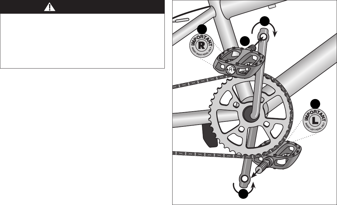
Figure 3.15
❶ Match the pedal marked R with the right-hand crank arm,
and match the pedal marked L with the le-hand crank arm.
Figure 3.15
❷ Place the threaded pedal into the threaded hole on the
crank arm.
❸ By hand, slowly turn the spindle the correct direcon.
Clockwise for right side pedal, counterclockwise for le side
pedal. Important! Stop if you feel resistance! This may be
an indicaon the spindle is entering the hole at an
angle. Remove the spindle and repeat step two and three.
❹ If the spindle is entering the hole cleanly then use a 15 mm
wrench or pliers to ghten completely.
❺ Repeat steps 1- 4 for the remaining pedal.
ATTACH THE PEDALS
• Aachment of an incorrect pedal into a crank arm can strip
pedal threads and cause irreparable damage. Visually
match the R and L sckers on the pedal and crank arm
before aaching the pedals. Before your rst ride, please
check to ensure your pedals are aached correctly.
• It is very important that you check the crank set for correct
adjustment and ghtness before riding your bicycle.
The left pedal turns
counter-clockwise and
the right pedal turns
clockwise.
1
1
2
3
3