
User's Manual


BASE UNIT
Front Panel Side Panel
Rear Panel
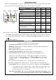
1. ALARM OUT SELECTOR: Set the Alarm Relay Output terminals as +12VDC output or dry contacts
when the relay activates.
2. Terminal Board (Refer to the APPENDIX A-5): One pair of Alarm Relay contacts, +12VDC (12~15V
/200mA max.) output and Ground terminal, three wire sensor inputs, two Aux. Outputs.
3. COM1 (Refer to the APPENDIX A-2, A-3, A-6): Communication port for RS-232 Adaptor, Ethernet
Adaptor or GSM module. (RS-232 adaptor, GSM module and Ethernet adaptor are optional).
4. COM2 (Refer to the APPENDIX A-4): Communication port for X-10 Power Line Interface controller
and RS-485 interface (reserved).
5. AUX Audio (Refer to the APPENDIX A-6): Audio I/O for GSM module (GSM module is optional).
Key Board & Status Display
Emergency Buttons
Speaker
LCD Display
Key Board
LED status
Microphone
To trigger the Emergency help,
press both buttons simultaneously.
Speaker Volume Control
Power adaptor I/P
2. Terminal Board
Tele
p
hone Line I/P
Phone Set Connecto
r
Wire Duc
t
1.ALARM OUT SELECTO
R
3.COM1
4.COM2
5.AUX. Audio
3
Key A & AWAY ARM
Key B & HOME ARM
Key C, STATUS CLEAR & PAUSE
Key D, DISARM & ENTER
Key 1 & Hands-free Telephone
Key 2 & X-10 Switch Control
Key 3 & Alarm Relay Control
Key 4 & Door Open (Reserved)
YES NO FUNC / ESC