
User Manual


DigiLink US, ECO DC Version
DIGUSDCECO Issue 1
6
Installation
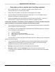
The following procedure must be adhered to when installing the DigiLink paging system. Ensure you have
taken into consideration all of the above information before selecting the location for your transmitter. If in doubt
consult your dealer.
1 Remove the cover from the DigiLink transmitter unit by unscrewing the two Pozi head screws located at
the top and bottom of the unit (see Diagram 1).
2 Carefully lift off the cover and set aside.
3 The transmitter should be fixed to an even wall surface using suitable screws fitted through the three
holes provided in the chassis plate. Hold the chassis up to the chosen location and with the aid of a
pencil mark the position of the mounting holes.
Warning: Do not use the chassis plate as a template for drilling the holes into the wall. Hammer drills vibrating
through the chassis may irreparably damage the quartz crystals on the printed circuit boards.
4 Place the DigiLink transmitter over the mounting holes and secure the unit with suitable screws. Check
that the chassis plate does not bend and that the screws do not snag or pinch any of the internal cables.
5 Connect the antenna to the unit via the BNC connector located at the top of the housing. If the antenna
is an external antenna, or an antenna which is separate from the transmitter unit itself, ensure that the
previous criteria covered under the section headed Location of the Hardware, have been strictly
adhered to (also see section headed Other Antennas).
6 Connect the input cables to the zone terminals. Unless the unit has been specifically configured for
voltage input, these should be simple “dry” (no voltage) contacts only (i.e. isolated switch or relay
contacts).
If configured for voltage input (5-18V dc), the jumper link beside the relevant terminal must be
positioned nearest the “V” symbol marked on the circuit board (see diagram on page 9).
If in doubt, check with your dealer before proceeding; incorrect connection may cause
permanent damage.
7 Connect the power input lead to the + and – terminals provided (see diagram on page 9). Voltage must
be 12 to 13.8V dc max.
8 Replace the cover and refit the two retaining screws.
9 With power applied, the red Power LED on the front fascia of the unit will blink continuously after
automatic activation of zone 8. This indicates that the system is running and that the power source is
good. The red LED will remain off during transmission repeat periods, or when the power source falls
below 10.5V dc.
10 The system is now active and will transmit the pre-programmed message for each of the zones when
triggered. Repeat transmissions and other programmed parameters (e.g. battery low message) will be
identified on the Configuration Data sheet(s) supplied with the system.
A “Battery Low” message will be transmitted when the voltage falls below a pre-programmed value. The
default setting is 10.5V dc.