
User Manual

DigiLink US, ECO Mains Version
DIGUSACECO Issue 1
6
Installation
The following procedure must be adhered to when installing the DigiLink paging system. Ensure you have
taken into consideration all of the above information before selecting the location for your transmitter. If in doubt
please consult your dealer.
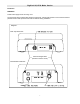
1 Remove the cover from the DigiLink transmitter unit by slackening the four Pozi head screws located at
the top and bottom of the unit (see Diagram 1).
2 Carefully lift off the cover and set aside.
3 The transmitter should be fixed to an even wall surface using suitable screws fitted through the three
holes provided in the chassis plate. Hold the chassis up to the chosen location and with the aid of a
pencil mark the position of the mounting holes.
Warning: Do not use the chassis plate as a template for drilling the holes into the wall. Hammer drills vibrating
through the chassis may irreparably damage the quartz crystals on the printed circuit boards.
4 Place the DigiLink transmitter over the mounting holes and secure the unit with suitable screws. Check
that the chassis plate does not bend and that the screws do not snag or pinch any of the internal cables.
5 Connect the antenna to the unit via the BNC connector located at the top of the housing. If the antenna
is an external antenna, or an antenna which is separate from the transmitter unit itself, ensure that the
previous criteria covered under the section headed Location of the Hardware, have been strictly
adhered to (also see section headed Other Antennas).
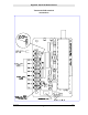
6 Connect the input cables to the zone terminals. Unless the unit has been specifically configured for
voltage input, these should be simple “dry” (no voltage) contacts only (i.e. isolated switch or relay
contacts).
If configured for voltage input (5-18V dc), the jumper link beside the relevant terminal must be
positioned nearest the “V” symbol marked on the circuit board (see diagram on page 9).
If in doubt, check with your dealer before proceeding; incorrect connection may cause
permanent damage.
7 If the unit is supplied with a sealed lead acid battery, plug together the two connector halves on the
battery lead. The battery will now be in circuit and the unit will power up.
8 Replace the cover and re-tighten the four retaining screws.
9 Finally, after checking all connections, connect the mains cable supplied to a suitable isolated, fused
spur or switched wall outlet. With mains power correctly applied, the red LED on the base of the unit will
light and Zone 8 will auto-trigger to indicate successful initialization.
10 The system is now active and will transmit the pre-programmed message for each of the zones when
triggered. Repeat transmissions and other programmed parameters (e.g. battery low message) will be
identified on the Configuration Data sheet(s) supplied with the system.