
User guide


CUEMIX FX
81
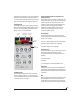
Output level
The Output Level meter (Figure 10-26) displays the
peaks of the output signal. Trim is applied before
the Output Level meter.
Peak/RMS modes
In RMS mode the compressor uses RMS values (a
computational method for determining overall
loudness) to measure the input level. In Peak mode,
the compressor uses signal peaks to determine the
input level. RMS mode will let peaks through
because the detector sidechain is only looking at
the average signal level. Peak mode will react to
brief peaks. Peak mode is generally used for drums,
percussion and other source material with strong
transients, while RMS mode is mostly used for
everything else.
The input meters show either the peak level or the
RMS level, depending on the mode.
Leveler
The Leveler™ (Figure 10-26) provides an accurate
model of the legendary Teletronix™ LA-2A®
optical compressor, known for its unique and
highly sought-after Automatic Gain Control
(AGC) characteristics. The UltraLite-mk3 Leveler
faithfully models the LA-2A using the on-board
DSP with 32-bit floating point precision.
A model of an optical compressor
The simplest description of an optical leveling
amplifier device is a light shining on a photore-
sistor. The intensity of the light source is
proportional to the audio signal, and the resistance
of the photoresistor is in turn inversely
proportional to the intensity of the light. Photore-
sistors respond quite quickly to increases in light
intensity, yet return to their dark resistance very
slowly. Thus, incorporation of the photoresistor
into an attenuator followed by an amplifier which
provides make-up gain produces a signal which
maintains a constant overall loudness.
Automatic gain control using light
The the Automatic Gain Control (AGC) circuit of
the LA-2A uses a vintage opto-coupler known by
its model number (T4). The T4 contains an
electroluminescent panel (ELP) and photoresistor
mounted so that the emission of the panel
modulates the resistance. An ELP consists of a thin
layer of phosphorescent material sandwiched
between two insulated electrodes to form a
capacitor. Making one of the electrodes
transparent allows the light to escape. These
devices are essentially glow-in-the-dark paint on a
piece of foil covered by metalized glass or plastic,
and are the same devices used in low-power night
lights. Unfortunately, these devices need high
voltages to operate, and are best driven by tube
circuits which can supply voltage swings of several
hundred volts.
Response characteristics
Once the light has faded away, the photoresistor
then decays back to its dark state. The shape of the
decay curve varies depending on how bright the
light was, and how long the light lasted. A general
rule of thumb is that the louder the program, the
slower the release. Typically, the release can take up
to and over one minute. One thing to keep in mind
when using these types of devices is that the typical
concepts of compression ratio, attack, release, and
threshold do not apply. The light intensity is
determined by the highly non-linear interactions
of the input signal, AGC circuit, and ELP, and thus
exhibit a strong program dependence that is
impossible to describe without the mind-numbing
mathematics of statistical mechanics. The actual
results, however, can be almost mystical: even
when you feed the same material (a loop perhaps)
through the Leveler twice, you’ll often see a new
response the second time through a loop, complete
with unique attack times, release times and
compression ratios. Furthermore, two different
input signals with the same RMS levels may be
leveled in a drastically different manner.