
MDT5N25 & MDT5N40 Ice Maker-Dispenser Service Manual
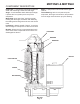
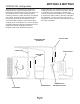
Table Of Contents
- Table of Contents
- FOR THE INSTALLER: Specifications Page 2
- FOR THE INSTALLER: Environmental Limitations Page 3
- FOR THE INSTALLER Page 4
- FOR THE INSTALLER: Wall Mount Kit Page 5
- FOR THE PLUMBER Page 6
- FOR THE ELECTRICIAN Page 7
- FOR THE INSTALLER: Final Check List Page 8
- INITIAL START UP Page 9
- COMPONENT DESCRIPTION Page 10
- COMPONENT DESCRIPTION Page 11
- COMPONENT DESCRIPTION: Control Box Page 12
- ELECTRICAL SEQUENCE Page 13
- OPERATION: Water Page 14
- OPERATION: Refrigeration Page 15
- OPERATION: Ice Vending Page 16
- DISPENSE AREA SANITATION Page 17
- CLEANING and SANITIZING Page 18
- MAINTENANCE AND CLEANING Page 19
- SERVICE DIAGNOSIS Page 21
- SERVICE DIAGNOSIS: Circuit Board Page 23
- REMOVAL AND REPLACEMENT Page 24
- REMOVAL AND REPLACEMENT: Bearing And Breaker Page 25
- REMOVAL AND REPLACEMENT: Water Seal Page 27
- TO REMOVE AND REPAIR THE GEARMOTOR ASSEMBLY Page 29
- REFRIGERATION SERVICE: R-404A (HP62) Page 30
- REFRIGERATION SERVICE Page 31
- CIRCUIT BOARD SERVICE Page 32
- LIQUID CHARGING Page 32
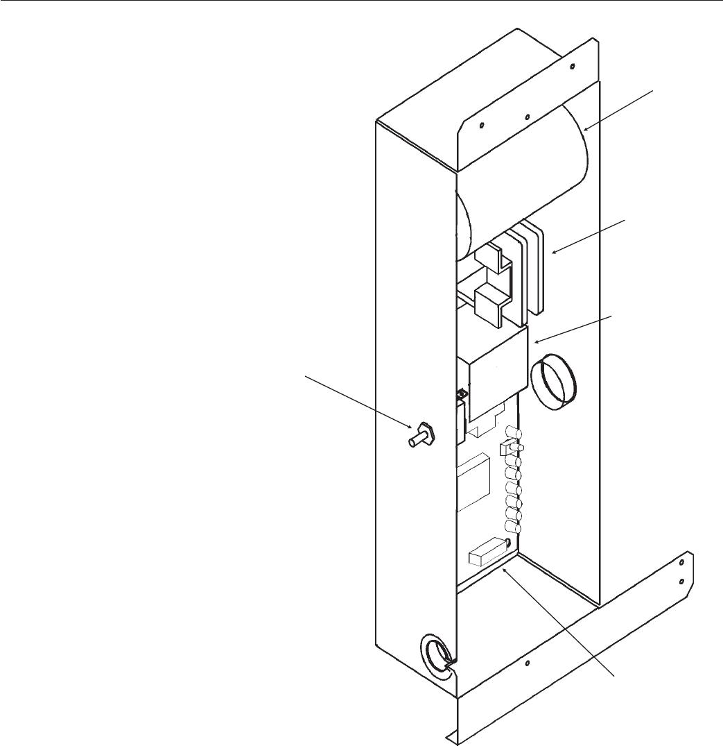
COMPONENT DESCRIPTION: Control Box
Circuit Board:
The circuit board receives
input signals from several
sensors and translates them to
control the electrical power
supply to the various loads.
The sensors include:
·
Touch Free ice or water.
·
Ice level in the bin.
·
Water level in the reservoir.
The loads include:
·
Compressor contactor
·
Fan motor
·
Bin drive motor
·
Auger drive motor
·
Water solenoid.
In addition, a “Clean” switch is
available to temporarily disable
the Touch-Free sensors for
cleaning of the splash panel.
On/Off Switch: Manual
control for the machine.
Contactor: A definite purpose
contactor connecting the
compressor to the power
supply.
Potential Relay: The
compressor start relay.
MDT5N25 & MDT5N40
May 2001
Page 12
CONTACTOR
CIRCUIT
BOARD
START
CAPACITOR
POTENTIAL
RELAY
ON-OFF
SWITCH