
MDT5N25 & MDT5N40 Ice Maker-Dispenser Service Manual
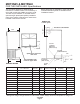
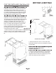

Table Of Contents
- Table of Contents
- FOR THE INSTALLER: Specifications Page 2
- FOR THE INSTALLER: Environmental Limitations Page 3
- FOR THE INSTALLER Page 4
- FOR THE INSTALLER: Wall Mount Kit Page 5
- FOR THE PLUMBER Page 6
- FOR THE ELECTRICIAN Page 7
- FOR THE INSTALLER: Final Check List Page 8
- INITIAL START UP Page 9
- COMPONENT DESCRIPTION Page 10
- COMPONENT DESCRIPTION Page 11
- COMPONENT DESCRIPTION: Control Box Page 12
- ELECTRICAL SEQUENCE Page 13
- OPERATION: Water Page 14
- OPERATION: Refrigeration Page 15
- OPERATION: Ice Vending Page 16
- DISPENSE AREA SANITATION Page 17
- CLEANING and SANITIZING Page 18
- MAINTENANCE AND CLEANING Page 19
- SERVICE DIAGNOSIS Page 21
- SERVICE DIAGNOSIS: Circuit Board Page 23
- REMOVAL AND REPLACEMENT Page 24
- REMOVAL AND REPLACEMENT: Bearing And Breaker Page 25
- REMOVAL AND REPLACEMENT: Water Seal Page 27
- TO REMOVE AND REPAIR THE GEARMOTOR ASSEMBLY Page 29
- REFRIGERATION SERVICE: R-404A (HP62) Page 30
- REFRIGERATION SERVICE Page 31
- CIRCUIT BOARD SERVICE Page 32
- LIQUID CHARGING Page 32
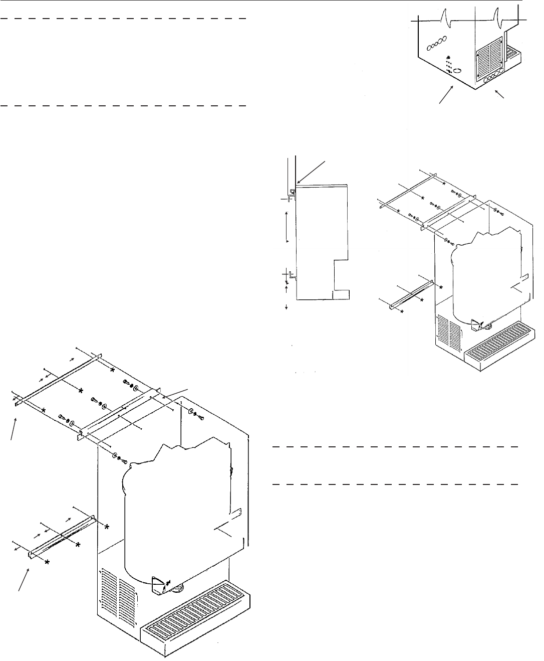
FOR THE INSTALLER: Wall Mount Kit
CAUTION
It is recommended that the wall mounting
installation be done by an experienced contractor.
The weight of the machine when in use may
exceed 350 pounds. The unit should be mounted
on a solid, rigid wall with proper fasteners for that
type of wall and of adequate strength to support
the weight of the machine when in use.
Clearance between the wall and the icemaker is a
maximum of 1 inch. Check utility connections first.
The electrical junction box will have to be removed,
and the electrical connections made inside the
cabinet in compliance with local codes. The
plumbing connections may be made through the
base, or at either side through the pre-punched
holes, using standard plumbing practices.
Interior plumbing lines must be disconnected from
the original connections and plugged when
routing through the side or base.
1. Remove machine top. Attach bracket “A” to
machine using (3) nuts, (3) flat washers, (3) lock
washers, and (3) 5/16-18 bolts received with the
kit.
2. Mount brackets “B” and “C” to the wall at the
dimensions shown for the unit. (hardware for this is
not included).
Use fasteners and wall of sufficient strength to
carry the use and weight of the
icemaker-dispenser.
3. Lift unit up and hook bracket “A” over bracket
“B”. Slide unit until the two remaining holes are
aligned and secure with the remaining (2) 1/4-20
bolts, flat washers and lock washers.
MDT5N25 & MDT5N40
May 2001
Page 5
7.83
SIDE
ROUTIN
BASE
HOLE
DO NOT LIFT ON SINK
1" CLEARANCE
B
A
C
16"
16"
12"
12"
MDT6N40=38.6"
MTD6N25=30"