
MDT5N25 & MDT5N40 Ice Maker-Dispenser Service Manual
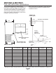
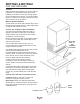
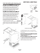
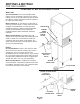
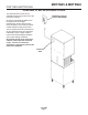

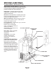
Table Of Contents
- Table of Contents
- FOR THE INSTALLER: Specifications Page 2
- FOR THE INSTALLER: Environmental Limitations Page 3
- FOR THE INSTALLER Page 4
- FOR THE INSTALLER: Wall Mount Kit Page 5
- FOR THE PLUMBER Page 6
- FOR THE ELECTRICIAN Page 7
- FOR THE INSTALLER: Final Check List Page 8
- INITIAL START UP Page 9
- COMPONENT DESCRIPTION Page 10
- COMPONENT DESCRIPTION Page 11
- COMPONENT DESCRIPTION: Control Box Page 12
- ELECTRICAL SEQUENCE Page 13
- OPERATION: Water Page 14
- OPERATION: Refrigeration Page 15
- OPERATION: Ice Vending Page 16
- DISPENSE AREA SANITATION Page 17
- CLEANING and SANITIZING Page 18
- MAINTENANCE AND CLEANING Page 19
- SERVICE DIAGNOSIS Page 21
- SERVICE DIAGNOSIS: Circuit Board Page 23
- REMOVAL AND REPLACEMENT Page 24
- REMOVAL AND REPLACEMENT: Bearing And Breaker Page 25
- REMOVAL AND REPLACEMENT: Water Seal Page 27
- TO REMOVE AND REPAIR THE GEARMOTOR ASSEMBLY Page 29
- REFRIGERATION SERVICE: R-404A (HP62) Page 30
- REFRIGERATION SERVICE Page 31
- CIRCUIT BOARD SERVICE Page 32
- LIQUID CHARGING Page 32
FOR THE PLUMBER
CONFORM TO ALL APPLICABLE CODES
Water Inlet
Air Cooled Models: The recommended water
supply is clean, cold water. Use 3/8" O.D. copper
tubing, connect to the 3/8" male flare at the back of
the cabinet. Install a hand valve near the machine
to control the water supply.
Water Treatment: In most areas, a water filter of
some type will be useful. In areas where the water
is highly concentrated with minerals the water
should be tested by a water treatment specialist,
and the recommendations of the specialist
regarding filtration and/or treatment should be
followed.
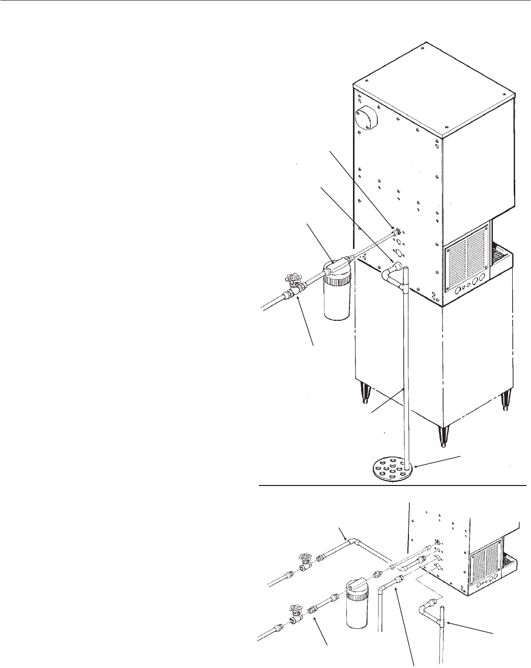
Water Cooled Models: A separate 3/8" O.D.
copper line is recommended, with a separate hand
valve to control it. It is connected to a 3/8" FPT
condenser inlet at the back of the cabinet. The
water pressure to all lines must always be above
20 psig, and below 80 psig.
Drains
Air Cooled Models: There is one 3/4" FPT drain
at the back of the cabinet, the drain line is of the
gravity type, and 1/4 inch per foot fall is an
acceptable pitch for the drain tubing. There should
be a vent at the highest point of the drain line, and
the ideal drain receptacle would be a trapped and
vented floor drain. Use only 3/4" rigid tubing.
Water Cooled Models: In addition to the above
mentioned drain, a separate condenser drain must
be installed. Connect it to the 1/2" condenser drain
connection at the back of the cabinet.
MDT5N25 & MDT5N40
May 2001
Page 6
WATER INLET
CABINET
DRAIN
OPTIONAL
WATER
FILTER
WATER INLET
SHUT OFF
VALVE
VENTED
DRAIN TUBE
FLOOR DRAIN
WATER COOLED DETAIL
Condenser
WATER INLET
POTABLE
WATER INLET
Condenser
DRAIN
CABINET
DRAIN