
MDT5N25 & MDT5N40 Ice Maker-Dispenser Service Manual
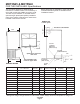
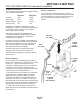
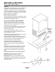
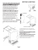
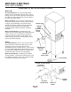
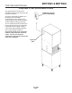

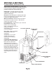
Table Of Contents
- Table of Contents
- FOR THE INSTALLER: Specifications Page 2
- FOR THE INSTALLER: Environmental Limitations Page 3
- FOR THE INSTALLER Page 4
- FOR THE INSTALLER: Wall Mount Kit Page 5
- FOR THE PLUMBER Page 6
- FOR THE ELECTRICIAN Page 7
- FOR THE INSTALLER: Final Check List Page 8
- INITIAL START UP Page 9
- COMPONENT DESCRIPTION Page 10
- COMPONENT DESCRIPTION Page 11
- COMPONENT DESCRIPTION: Control Box Page 12
- ELECTRICAL SEQUENCE Page 13
- OPERATION: Water Page 14
- OPERATION: Refrigeration Page 15
- OPERATION: Ice Vending Page 16
- DISPENSE AREA SANITATION Page 17
- CLEANING and SANITIZING Page 18
- MAINTENANCE AND CLEANING Page 19
- SERVICE DIAGNOSIS Page 21
- SERVICE DIAGNOSIS: Circuit Board Page 23
- REMOVAL AND REPLACEMENT Page 24
- REMOVAL AND REPLACEMENT: Bearing And Breaker Page 25
- REMOVAL AND REPLACEMENT: Water Seal Page 27
- TO REMOVE AND REPAIR THE GEARMOTOR ASSEMBLY Page 29
- REFRIGERATION SERVICE: R-404A (HP62) Page 30
- REFRIGERATION SERVICE Page 31
- CIRCUIT BOARD SERVICE Page 32
- LIQUID CHARGING Page 32
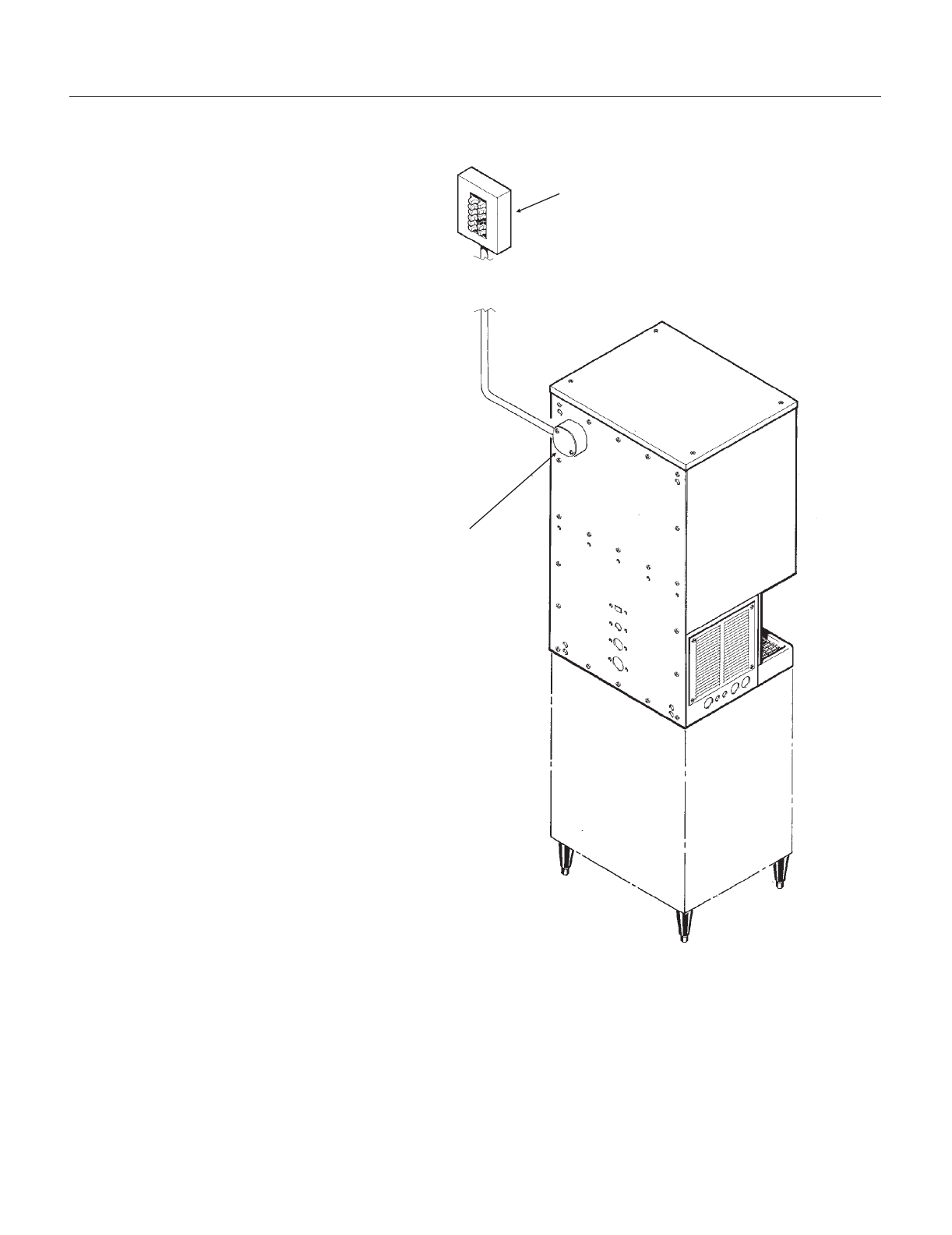
FOR THE ELECTRICIAN
CONFORM TO ALL APPLICABLE CODES
The electrical power to the unit is
supplied through the junction box at the
rear of the machine.
Check the nameplate (located on the
back panel) for the voltage
requirements, and for the minimum
circuit ampacity. The machine requires
a solid chassis to earth ground wire.
The ice maker should be connected to
its own electrical circuit so it would be
individually fused. Voltage variation
must remain within design limitations,
even under starting conditions.
All external wiring must conform to
national, state, and local electrical
codes. The use of a licensed
electrician is required to perform the
electrical installation.
MDT5N25 & MDT5N40
July 2003
Page 7
JUNCTION
BOX
INDIVIDUAL CIRCUIT
FOR ICE DISPENSER