Installation and User’s Manual Models C1448, C1848, C2148W
C1448, C1848, C2148W Air and Water Cooled User Manual Introduction The design of this modular cuber is the result of years of experience and testing. Standard features include front accessible indicator lights and on-off switches that provide the user with fast access to critical information and easy operational control. When desired, optional controls can add features like ultrasonic bin ice level sensing, seven day programmable bin ice level setting, remote lock out and more.
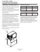
C1448, C1848, C2148W Air and Water Cooled User Manual Installation: Product Specifications Location Limitations: The product is designed to be installed indoors, in a controlled environment. Air cooled models discharge very warm air into the room out the back. Space must be allowed at the left side and back for air intake and discharge. Water cooled models discharge warm water into the building’s drain. Space needs to be provided on both sides and above for service access.
C1448, C1848, C2148W Air and Water Cooled User Manual Product Information The product is a modular cuber. That type of machine is designed to be placed on an ice storage bin or an ice dispenser. Many installations only require the matching bin, but some also require an adapter to be placed between the bin and the cuber or between the dispenser and the cuber. This product cannot be stacked. See the chart for application information.
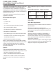
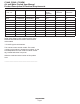
C1448, C1848, C2148W Air and Water Cooled User Manual Product Description & Electrical Requirements Dimensions w” x d” x h” Model Electrical Condenser 48 x 24 x 29 same same same same same same same same same C1448SA-32 C1448SW-32 C1448SA-3 C1448SW-3 C1848SA-32 C1848SW-32 C1848SA-3 C1848SW-3 C2148SW-32 C2148SW-3 208-230/60/1 208-230/60/1 208-230/60/3 208-230/60/3 208-230/60/1 208-230/60/1 208-230/60/3 208-230/60/3 208-230/60/1 208-230/60/3 Air Water Air Water Air Water Air Water Water Water Table no
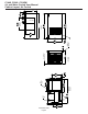
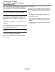
45.7 18.00 3/4" FPT DRAIN November 2006 Page 5 117.3 46.17 3/8" FPT WATER INLET AIR COOLED BACK VIEW 63.2 24.90 61.4 24.18 .88 DIA ELECTRICAL ACCESS 7.4 2.91 52.2 20.54 LEFT SIDE VIEW 61 24.00 1.57 REFRIGERATION AND ELECTRICAL CHASE 2.3 .92 LOUVER AND REMOVABLE FILTER AC UNITS ONLY 2.3 .92 73.7 29.00 46.5 18.30 121.9 48.00 FRONT VIEW 124.2 48.89 PLAN VIEW 48.00 REF. 57.8 22.75 MINIMUM BIN TOP OPENING 24.5 9.63 ICE DROP OPENING 22.9 9.00 5.1 2.00 24.00 REF.
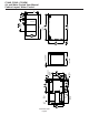
45.7 18.00 3/8" FPT WATER INLET November 2006 Page 6 WATER COOLED BACK VIEW 3/4" FPT DRAIN .88 DIA ELECTRICAL ACCESS 117.3 46.17 7.5 2.96 63.2 24.90 61.5 24.20 14.3 5.64 1/2" FPT CONDENSER DRAIN 9.4 3.70 56.1 22.09 3/8" FPT (C1448/1848) 1/2" FPT (C2148) CONDENSER WATER INLET 52.3 20.59 11.7 4.63 LEFT SIDE VIEW 61 24.00 1.57 REFRIGERATION AND ELECTRICAL CHASE 2.3 .92 73.7 29.00 46.5 18.30 121.9 48.00 FRONT VIEW 124.2 48.89 PLAN VIEW 48.00 REF. 57.8 22.
C1448, C1848, C2148W Air and Water Cooled User Manual Water The quality of the water supplied to the ice machine will have an impact on the time between cleanings and ultimately on the life of the product. There are two ways water can contain impurities: in suspension or in solution. Suspended solids can be filtered out. In solution or dissolved solids cannot be filtered, they must be diluted or treated. Water filters are recommended to remove suspended solids.
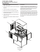
C1448, C1848, C2148W Air and Water Cooled User Manual Panel Removal 1. Locate and loosen the two screws at the front edge of the top panel. 2. Pull the front panel out at the top until it clears the top panel. 3. Lift the front panel up and off the machine. 4. Remove two screws at front edge of top panel. 5. Lift up the front of the top panel, push it back an inch, then lift to remove. 6. Locate and loosen the screw holding each side panel to the base. 7.
C1448, C1848, C2148W Air and Water Cooled User Manual Uncrate and Set Up Begin with unpacking the ice storage bin. Remove the carton, and using part of the carton as a cushion, tip the bin on its back to remove the skid and attach the legs or casters. Note: Turn the leg levelers in all the way and adjust after the ice machine is on top and in its selected location. Return the bin to an upright position.
C1448, C1848, C2148W Air and Water Cooled User Manual Plumbing Requirements All models require connection to cold, potable water. A hand actuated valve within site of the machine is required. Air cooled models have a single 3/8” FPT inlet water connection. Water cooled models have a 1/2" FPT drain fitting plus an additional 3/8” FPT condenser inlet water connection. Water Filters If connecting to water filtration, filter only the water to the reservoir, not to the condenser.
C1448, C1848, C2148W Air and Water Cooled User Manual Drains All models require drain tubing to be attached to them. Air cooled models have a single ¾” FPT drain fitting in the back of the cabinet. Water cooled models have the same fitting plus an additional ½” FPT drain fitting in the back of the cabinet. Install new tubing when replacing a prior ice machine, as the tubing will have been sized for the old model and might not be correct for this one.
C1448, C1848, C2148W Air and Water Cooled User Manual Electrical The machine is not supplied with a power cord, the machine should be hard-wired. The dataplate on the back of the cabinet details the power requirements, including voltage, phase, minimum circuit ampacity and maximum fuse size. HACR type circuit breakers may be used in place of fuses. Extension cords are not permitted. Use of a licensed electrician is recommended.
C1448, C1848, C2148W Air and Water Cooled User Manual Final Check List After connections, 1. Wash out the bin. If desired, the interior of the bin could be sanitized. 2. Locate the ice scoop (if supplied) and have it available for use when needed. Final Check List: 1. Is the unit located indoors in a controlled environment? 2. Is the unit located where it can receive adequate cooling air? 3. Has the correct electrical power been supplied to the machine? 4.
C1448, C1848, C2148W Air and Water Cooled User Manual Initial Start Up 1. Remove front panel. Check machine for any packing or wires rubbing moving parts. Note location of control board in upper left corner of the machine’s front. 2. Switch on the electrical power to the machine. Observe that some of the control’s indicator lights glow and its display shows O. 3. Open the water supply valve. Harvest continues until the ice is released as a unit and forces the curtain to open.
C1448, C1848, C2148W Air and Water Cooled User Manual Adjustments 1/8 - 3/16” bridge Bridge Thickness - For Service Tech Only 1. Push and hold Off till the machine stops. 2. Remove evaporator cover. 3. Remove curtain. 4. Use a box wrench and rotate the bridge thickness adjustment screw in 1/8 turn increments CW to increase bridge thickness. 5. Rotate CCW to decrease bridge thickness. Caution: Do not make the bridge too thin or the machine will not harvest properly.
C1448, C1848, C2148W Air and Water Cooled User Manual Water flush setting The water flush is factory set to the automatic position, suitable for most water conditions. The setting can be changed to one of 5 manual settings or left on automatic. Flush setting Water Type 1 - Minimum RO water or equivalent Status Power 2 - Moderate De-Scale Water 3 - Standard Factory Setting for typical water Off On To set: 1.
C1448, C1848, C2148W Air and Water Cooled User Manual Use and Operation Once started, the ice machine will automatically make ice until the bin or dispenser is full of ice. When ice level drops, the ice machine will resume making ice. Caution: Do not place anything on top of the ice machine, including the ice scoop. Debris and moisture from objects on top of the machine can work their way into the cabinet and cause serious damage. Damage caused by foreign material is not covered by warranty.
C1448, C1848, C2148W Air and Water Cooled User Manual Switches The two switches – on and off - can be accessed from the front of the machine. Status De-Scale Off • Certain dispenser applications where maximum ice level is not desired Use of control 02-4294-01 Graphic Rev.
C1448, C1848, C2148W Air and Water Cooled User Manual Options and Other Information Smart-Board Noise When this option is present there is an additional display panel in the area below the main control board. It is not visible when the front panel is on. The ice machine will make noise when it is in ice making mode. The compressor, fan motors if air cooled and water pump all produce some sound. It is also normal to hear some cracking just before the harvest cycle begins.
C1448, C1848, C2148W Air and Water Cooled User Manual Cleaning, Sanitation and Maintenance This ice system requires three types of maintenance: • Remove the build up of mineral scale from the ice machine’s water system and sensors. • Sanitize the ice machine’s water system and the ice storage bin or dispenser. • Clean or replace the air filter and clean the air cooled condenser (air cooled models only). It is the User’s responsibility to keep the ice machine and ice storage bin in a sanitary condition.
C1448, C1848, C2148W Air and Water Cooled User Manual 13. Remove water distributors from ice machine. Inspect each distributor for restricted orifice holes. Be sure all holes are full open. Squeeze tabs together, slide out until it stops, then lift to remove. 16. Mix a solution of locally approved sanitizer. Use an EPA approved food equipment sanitizer at the solution mix recommended by the sanitizer manufacturer.
C1448, C1848, C2148W Air and Water Cooled User Manual Air cooled condenser filter 1 Pull air filters from their louvered mounts. Exterior Panels 2 Wash the dust and grease off the filter. The front and side panels are durable stainless steel. Fingerprints, dust and grease will require cleaning with a good quality stainless steel cleaner. 3 Return them to their original positions. Do not operate the machine without the filter in place except during cleaning.
C1448, C1848, C2148W Air and Water Cooled User Manual What to do before calling for service Reasons the machine might shut itself off: • Lack of water. • Freeze cycle takes too long. • Harvest cycle takes too long. • High discharge temperature. • Controller self test failure. Check the following: 1. Has the water supply to the ice machine or building been shut off? If yes, the ice machine will automatically restart within 25 minutes after water begins to flow to it. 2.
SCOTSMAN ICE SYSTEMS 775 Corporate Woods Parkway Vernon Hills, IL 60061 800-726-8762 www.scotsman-ice.com 17-3083-02 Rev D.