Installation and User’s Manual for Modular Cuber Models C0322, C0522, C0722, C0330, C0530, C0630, C0830 and C1030
C0322 through C1030 Air and Water Cooled User Manual Introduction The design of this modular cuber is the result of years of experience and testing. Standard features include front accessible indicator lights and on-off switches that provide the user with fast access to critical information and easy operational control. Keep this manual for future reference.
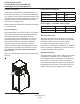
C0322 through C1030 Air and Water Cooled User Manual Installation: Product Specifications Location Limitations: Environmental Limitations The product is designed to be installed indoors, in a controlled environment. Air cooled models discharge very warm air into the room out the back. Space must be allowed at the left side and back for air intake and discharge. Water cooled models discharge warm water into the building’s drain. Space needs to be provided on both sides and above for service access.
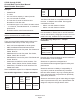
C0322 through C1030 Air and Water Cooled User Manual Model Number Description C0530, C0630, C0830, C1030 Example: • • • • • • • • C0322SA-1B C= cuber 03= nominal ice capacity in 100s of pounds 22= nominal width of cabinet S= Cube size. S=small or half dice cube. M=medium or full dice cube A=Condenser type. A=air cooled. W=water cooled -1=115 60 Hz, -32=208-230 60 Hz, -3= 208-230 3 phase 60 Hz B=Series revision code.
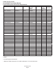
C0322 through C1030 Air and Water Cooled User Manual Product Description & Electrical Requirements Dimensions w" x d" x h" Model Series Electrical volts/Hz/ phase Condenser Minimum Circuit Ampacity Maximum Fuse Size* 22.75** x 24 x 23 C0322SA-1 A or B 115/60/1 Air 12.7 15 C0322SW-1 A or B 115/60/1 Water 11.9 15 C0322SA-32 A or B 208-230/60/1 Air 6.1 15 C0322SW-32 A or B 208-320/60/1 Water 5.6 15 C0522SA-1 A or B 115/60/1 Air 13.
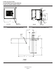
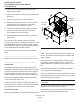
C0322 through C1030 Air and Water Cooled User Manual C0322 and C0522 Cabinet Layout 4.1 1.60 .88" DIA ELECTRICAL ACCESS 37 14.56 27.4 10.79 3/8" FPT WATER INLET 61 24.00 LOUVER AND REMOVABLE FILTER AC UNITS ONLY LEFT SIDE VIEW 3/4" FPT DRAIN 4.1 1.62 AIR COOLED BACK VIEW C0322, C0522 Air Cooled Side View 7.7 3.04 3.6 1.43 C0322, C0522 Air Cooled Back View 26 10.25 8.3 3.25 ULTRASONIC BIN LEVEL SENSOR (OPTIONAL) 5.1 2.00 5.1 2.00 ICE DROP OPENING 17.8 7.00 55.9 22.00 REF.
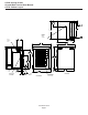
C0322 through C1030 Air and Water Cooled User Manual C0330, C0530, C0630 and C1030 Cabinet Layout 4.3 1.70 .88" DIA ELECTRICAL ACCESS 27.5 10.81 3/8" FPT WATER INLET 4.4 1.73 AIR COOLED BACK VIEW 3.7 1.48 37 14.59 7.8 3.06 61 24.00 3/4" FPT DRAIN LEFT SIDE VIEW C0330, C0530, C0630 Air Cooled Back View LOUVER AND REMOVABLE FILTER AC UNITS ONLY C0330, C0530, C0630 Air Cooled Side View 26 10.25 8.3 3.25 ULTRASONIC BIN LEVEL SENSOR (OPTIONAL) 5.1 2.00 5.1 2.00 ICE DROP OPENING 17.8 7.00 76.
C0322 through C1030 Air and Water Cooled User Manual C0722 Cabinet Layout 17.8 7.00 ICE DROP OPENING 5.1 2.00 24.00 REF. ULTRASONIC BIN LEVEL SENSOR (OPTIONAL) 8.3 3.25 26 10.25 20.2 7.94 .88" DIA. ELECTRICAL ACCESS 22.00 62.3 24.53 58.1 22.89 63.1 24.83 73.7 29.00 42.7 16.83 7.8 3.08 3/8" FPT WATER INLET AIR COOLED BACK VIEW 4.3 1.71 4.2 1.64 2.4 .93 61 24.00 3/4" FPT DRAIN LEFT SIDE VIEW 48.4 19.05 LOUVERS AND REMOVABLE FILTERS (2) AC UNITS ONLY November 2012 Page 7 55.9 22.
C0322 through C1030 Air and Water Cooled User Manual Water The quality of the water supplied to the ice machine will have an impact on the time between cleanings and ultimately on the life of the product. Water can contain impurities either in suspension or in solution. Suspended solids can be filtered out. In solution or dissolved solids cannot be filtered, they must be diluted or treated. Water filters are recommended to remove suspended solids. Some filters have treatment in them for suspended solids.
C0322 through C1030 Air and Water Cooled User Manual Panel Removal 1. Locate and loosen the two screws at the front edge of the top panel. 2. Pull the front panel out at the top until it clears the top panel. 6 3. Lift the front panel up and off the machine. 4 4. Remove two screws at the front of the top panel. Lift up the front of the top panel, push the top panel back an inch, then lift to remove. 1. Remove Screws 2 5. Locate and loosen the screw holding each side panel to the base.
C0322 through C1030 Air and Water Cooled User Manual Plumbing Requirements All models require connection to cold, potable water. A hand actuated valve within site of the machine is required. Air cooled models have a single 3/8” FPT inlet water connection; a 3/8” FPT to 3/8” male flare adapter is available from the local Scotsman distributor or from a hardware store.
C0322 through C1030 Air and Water Cooled User Manual Electrical The machine is not supplied with a power cord as the machine is designed to be permanently connected. The dataplate on the back of the cabinet details the power requirements, including voltage, phase, minimum circuit ampacity and maximum fuse size. HACR type circuit breakers may be used in place of fuses. Extension cords are not permitted. Use of a licensed electrician is recommended.
C0322 through C1030 Air and Water Cooled User Manual Final Check List After connections, 1. Wash out the bin. If desired, the interior of the bin could be sanitized. 2. Locate the ice scoop (if supplied) and have it available for use when needed. Final Check List: 1. Is the unit located indoors in a controlled environment? 2. Is the unit located where it can receive adequate cooling air? 3. Has the correct electrical power been supplied to the machine? 4. Have all the water supply connections been made? 5.
C0322 through C1030 Air and Water Cooled User Manual Initial Start Up 1. Remove front panel and evaporator cover. Check machine for any packing or wires rubbing moving parts. Note location of control board in upper left corner of the machine’s front. 2. Switch on the electrical power to the machine. Observe that some of the control’s indicator lights glow and its display shows O. 3. Open the water supply valve. 4. Push and release the ON button. The code display will begin to blink F.
C0322 through C1030 Air and Water Cooled User Manual Adjustments Ice Bridge Thickness Measurement Bridge Thickness - For the Service Tech Only Note: Indentations may be deeper on C0322 and C0330 1/8-3/16” bridge 1. Push and hold Off till the machine stops. 2. Remove evaporator cover. 3. Remove curtain. 4. Use a hex wrench and rotate the bridge thickness adjustment screw in 1/8 turn increments CW to increase bridge thickness. Rotate CCW to decrease bridge thickness.
C0322 through C1030 Air and Water Cooled User Manual Use and Operation Once started, the ice machine will automatically make ice until the bin or dispenser is full of ice. When ice level drops, the ice machine will resume making ice. Caution: Do not place anything on top of the ice machine, including the ice scoop. Debris and moisture from objects on top of the machine can work their way into the cabinet and cause serious damage. Damage caused by foreign material is not covered by warranty.
C0322 through C1030 Air and Water Cooled User Manual Control Switches The On and Off switch buttons are front accessible. De-scale Status Power Water Off On To switch the machine OFF, push and release the Off button. The machine will shut off at the end of the next cycle. To shut the machine off immediately, push and hold the Off button for 3 seconds. To switch the machine ON, push and release the On button. The machine will go through a start up process and then resume ice making.
C0322 through C1030 Air and Water Cooled User Manual Options Advanced Feature Board, kit #KSBU Ice When this option is present there is an additional display panel in the area below the main control board. It is not visible when the front panel is on. The cuber drops ice in large sections. That ice will break up into random parts as it falls into the bin, but some large sections may remain on top of the ice in the bin.
C0322 through C1030 Air and Water Cooled User Manual Cleaning, Sanitation and Maintenance This ice system requires three types of maintenance: • • • Remove the build up of mineral scale from the ice machine’s water system and sensors. Sanitize the ice machine’s water system and the ice storage bin or dispenser. Clean or replace the air filter and clean the air cooled condenser (air cooled models only). It is the User’s responsibility to keep the ice machine and ice storage bin in a sanitary condition.
C0322 through C1030 Air and Water Cooled User Manual 13. Remove water distributor from ice machine. Inspect distributor for restricted orifice holes. Be sure all holes are fully open. Squeeze Tabs Together, Slide Out Until it Stops, Then Lift to Remove A possible sanitizing solution may be made up by using one 2 oz packet of Stera Sheen Green Label sanitizer (available from Scotsman) and 2 gallons of clean, potable 95oF. to 115oF. water. 18.
C0322 through C1030 Air and Water Cooled User Manual Air cooled condenser filter 1. Pull air filter(s) forward from side panel. Air Filter 2. Wash the dust and grease off the filter. 3. Return it to its original position. Do not operate the machine without the filter in place except during cleaning. Air cooled condenser If the machine has been operated without a filter the air cooled condenser fins will need to be cleaned. They are located under the fan blades.
C0322 through C1030 Air and Water Cooled User Manual What to do before calling for service Reasons the machine might shut itself off: • • • • • Lack of water. Freeze cycle takes too long. Harvest cycle takes too long. High discharge temperature. Controller self test failure. Check the following: 1. Has the water supply to the ice machine or building been shut off? If yes, the ice machine will automatically restart within 25 minutes after water begins to flow to it. Curtain 2.
SCOTSMAN ICE SYSTEMS 775 Corporate Woods Parkway Vernon Hills, IL 60061 www.scotsman-ice.com 800-726-8762 17-3083-01 Rev B Print Rev E.