CMS1002R INTRODUCTION This manual is intended as a reference for the installation and service of a Scotsman ice maker model CMS1002. This model is a remote condenser cuber, 30" wide and should be connected to a Scotsman remote condenser. TABLE OF CONTENTS Page Specifications . . . . . . . . . . . . . . . . . . . . . . . . . . . . . . . . . . . . . . 2 Environmental Limitations . . . . . . . . . . . . . . . . . . . . . . . . . . . . . . . . 3 For the Installer Machine & Bin Assembly . . . . . . . . . . .
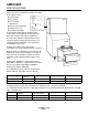
CMS1002R SPECIFICATIONS Always refer to the nameplate, located on the back of the cabinet, for the: • model number, • serial number, • basic electrical requirements, • minimum circuit ampacity, • maximum fuse size, • and refrigerant charge. A serial number plate with the model number, serial number and refrigerant charge is located behind the front panel, below the control box. The unit comes from the factory with the correct refrigerant charge contained in the receiver.
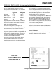
CMS1002R FOR THE INSTALLER: Environmental Limitations Installation Limitations Water Limitations The ice making portion of this ice system is designed to be installed indoors, in a controlled environment. An ice machine is a food manufacturing plant; it takes a raw material, water, and turns it into a food product, ice. The purity of the water is very important in obtaining pure ice and in maximizing product life.
CMS1002R FOR THE INSTALLER: Machine & Bin Assembly Overview: Ice Maker: This ice system is comprised of 4 major assemblies: 1. Arrange for proper electric, water and drain. See instructions for the plumber and for the electrician. 1. The ice storage bin. 2. The ice maker itself. 2. Position the ice storage bin in the selected location which should have a minimum room temperature of 50-degrees F. and maximum room temperature of 100 degrees F. 3. The interconnecting refrigerant lines. 4.
CMS1002R FOR THE PLUMBER Water Supply The recommended water supply line is a 3/8-inch O.D. tubing with a minimum operating pressure of 20 PSIG and a maximum of 80 PSIG. Connect to cold water supply line with standard plumbing fittings, with shut off valve installed in an accessible place between the water supply and the cuber. ln some cases a plumber will be required. The drains to be installed must conform with the local plumbing codes. Use only 3/4" rigid tubing.
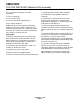
CMS1002R FOR THE INSTALLER: Remote Condenser Locate the condenser as near as possible to the interior location of the ice maker. Location of the condenser is limited by the specific length of pre-charged refrigerant tubing supplied for the application. The pre-charged tubing connects the icemaker to the remote condenser. The condenser must be above the ice maker. SCOTSMAN REMOTE CONDENSER Select the best available location, protecting the condenser from extremes of dirt, dust, and sun.
CMS1002R FOR THE INSTALLER: Coupling Instructions /////////////////////////////CAUTION///////////////////////////// The couplings on the sets of precharged lines are self sealing when installed properly. Carefully follow the instructions: ////////////////////////////////////////////////////////////////////////// 1. Remove the protector caps and plugs. Wipe the seats and threaded surfaces with a clean cloth to be certain that no foreign matter remains on them. 2.
CMS1002R FOR THE ELECTRICIAN: Electrical Connections See the NAMEPLATE for current requirements to determine wire size to be used for electrical hookup. The cuber requires a solid chassis to chassis earth ground wire. See Wiring Diagram. Be certain the cuber is connected to its own electrical circuit and individually fused. Voltage variation should not exceed ten percent of the nameplate rating, even under starting conditions.
CMS1002R FOR THE INSTALLER: Final Check List 1. Is the ice maker cabinet in a room where ambient temperatures are within the minimum and maximum temperatures specified? 2. Is there clearance at both sides of the cabinet and at the back and top for service and utility connections? 3. Has water supply pressure been checked to insure a minimum of 20 PSIG and a maximum of 80 PSIG operating pressure? 4. Is the cabinet level? 5. Check that any shipping material has been removed from inside the cabinet. 6.
CMS1002R INITIAL START UP Remote Condenser: EVAPORATOR COVER 1. Check that all connections have been made. Ice Maker: 1. Remove front panel by pulling out to unsnap. 2. Remove two screws and the control box cover. 3. Remove the evaporator cover. 4. Remove the left side service panel. 5. Check that the ON/WASH/OFF rocker switch and the Compressor ON-OFF toggle switch are in the OFF position, on the control box. 6. Locate and open the king (service) valve on the receiver.
CMS1002R INITIAL START UP 14. Check CUBE SIZE CUBES (ACTUAL SIZE) The dimensions of the cubes are fixed by the size and shape of the molds on the evaporator plate, except that the thickness of the cube MAY need to be adjusted at start up. There is only one size of cube that is correct; adjusting the cube size control to that size of cube will allow the ice maker to produce ice at its most efficient size.
CMS1002R ADJUSTMENTS Adjustment Of The Timer & Switch Assembly TIMER CAM POSITIONS ACTUATOR MICROSWITCH CAM & SHAFT One complete revolution of the cam on the timer represents eight minutes. If left as factory set, four and one-half minutes comprise the freezing cycle portion during cam rotation, and the final three and one-half minutes is the defrost/harvest cycle. Rotating the shaft of the timer cam clockwise will put the ice machine in the freeze or harvest cycle.
CMS1002R COMPONENT DESCRIPTION Compressor Contactor Hot Gas Solenoid Valve The compressor contactor carries the compressor line current. The contactor is wired so any control in the pilot circuit, such as the bin control, and high pressure controls, etc., will cause the contactor holding coil to be de energized, when the control contact OPENS, thereby breaking the circuit to the compressor. The hot gas solenoid valve opens only during the harvest cycle.
CMS1002R COMPONENT DESCRIPTION Ice Level Control This electronic control uses sound waves to measure the distance between the bottom of the ice machine and the top of the ice in the bin. It is designed to control the machines ice production to maintain that distance. The control is adjustable so that the ice machine will maintain a certain height of ice. It will not fill any closer to the ice machine than 8", and will not work if the distance to the bottom of the bin is greater than 8 feet.
CMS1002R COMPONENT DESCRIPTION Electric Water Inlet Valve Reservoir The water inlet solenoid valve fills the reservoir assembly with water. Excess water overflows out the overflow standpipe located at the back of the reservoir. This action fills and rinses the reservoir during each harvest cycle. The flow rate is .75 g.p.m. The reservoir, located below the evaporators, stores the inlet water charge, and collects the water that flows over the evaporator plates.
CMS1002R SERVICE SPECIFICATIONS When servicing a machine, it’s helpful to compare that unit’s operating characteristics to those of a new, clean, normally operating machine. What follows is that type of information: COMPONENTS Timer: Makes one complete revolution in 8 minutes. The harvest time is factory preset at 2 1⁄4 minutes. The harvest time is adjustable as required. Inlet Water Valve: Opens and admits 3⁄4 gallon per minute during the harvest cycle.
CMS1002R CLEANING /////////////////////////////////////////////////////////////////////////////////////////////////////////////////////////////////////////////////////////////////// A Scotsman Ice System represents a sizable investment of time and money in any company’s business. In order to receive the best return for that investment, it MUST receive periodic maintenance. Maintenance and Cleaning should be scheduled at a minimum of twice per year.
CMS1002R CLEANING SANITIZE WATER SYSTEM SCOTSMAN REMOTE CONDENSER 1. Remove and discard all ice from the bin. 1. Disconnect electrical power at the icemaker. 2. Remove front panel. ///////////////////////////////WARNING/////////////////////////// 3. Drain the reservoir Disconnect electrical power before beginning. 4. Prepare 2 gallons of an approved sanitizer solution in accordance with the instructions on the package. //////////////////////////////////////////////////////////////////////////// 5.
CMS1002R FREEZING CYCLE OPERATION Water from the sump assembly is pumped to the water distributor system at the top of each evaporator plate. From the water distributor the water cascades by gravity over all cells of the plate and to the sump assembly below. At the beginning of the freezing cycle, the electrical circuit is completed to the compressor and the water pump. The water pump operates continuously, through both the freezing cycle and the harvest cycle.
CMS1002R HARVEST CYCLE - HOT GAS BYPASS When the timer switches the icemaker into the harvest cycle, high pressure, high temperature gas refrigerant being discharged from the compressor is diverted from the condenser through the hot gas solenoid valve into each evaporator plate. During this cycle, the refrigerant bypasses the condenser.
CMS1002R SERVICE DIAGNOSIS SYMPTOM POSSIBLE CAUSE PROBABLE CORRECTION No ice, machine does not run 1. No electrical power 1. Restore power 2. Circuit breaker tripped or fuse blown 2. Reset breaker or replace fuse, check for electrical fault. 3. High pressure control open. 3. Reset HPC, check fan motor for proper operation, and condenser coil for dirt. 4. Bin level control holding machine off 4. Check ice level control circuit. See page 25. 5. High temp. cut out open 5.
CMS1002R SERVICE DIAGNOSIS SYMPTOM POSSIBLE CAUSE PROBABLE CORRECTION Low ice production 3. High head pressure, a result of a dirty condenser 3. Clean condenser, check fan motor 4. Hot gas valve leaks thru 4. Replace hot gas valve 5. High air temp. for condenser. 5. If possible, reduce condenser air inlet temperature. 1. Cube size control will not close 1. Check temp. of suction line, cube size control will not close if temp. too high. If temp. low enough, replace cube size control 2.
CMS1002R SERVICE DIAGNOSIS: Ice Level Control Circuit CONDITION DETERMINE CAUSE Ice Machine does not run, it has power to it, the high pressure control is closed, the on/off switch is set to ON (the compressor will not operate until the liquid line valve opens, but the pump should be working if there is no ice in the bin). PROBABLE CORRECTION A. Listen for a ticking sound from transducer. If no noise, go to C. If there is a noise, check for a light on the board (models built after 4/93).
CMS1002R REMOVAL AND REPLACEMENT TRANSDUCER 1. Disconnect electrical power BEFORE removing transducer. 5. Unplug transducer and remove from the machine. 2. Open bin door and locate the transducer socket. 6. Reverse steps 1-5 to reassemble. 3. Twist inner portion of transducer counterclockwise and push up gently. 4. Pull transponder down until plug connection is accessible.
CMS1002R REMOVAL AND REPLACEMENT /////////////////////////////////WARNING////////////////////////////// Cube Size Control Disconnect electrical power before beginning. To remove the cube size control: ///////////////////////////////////////////////////////////////////////////////// 1. Remove front panel. Water Distributor Tubes And Manifold Tubes 2. Remove cover from control box. To remove the water distributor tube and manifold tube: 3.
CMS1002R REMOVAL AND REPLACEMENT //////////////////////////////WARNING////////////////////////////////// Inlet Water Solenoid Valve Assembly Disconnect electrical power before beginning. To remove the inlet water solenoid valve assembly: ////////////////////////////////////////////////////////////////////////////////// 1. Shut OFF water supply to machine. Water Pump 2. Loosen and remove outlet water line from the inlet water solenoid valve assembly. 1. Remove front panel. 3.
CMS1002R REMOVAL AND REPLACEMENT Head Pressure Control Valve Thermostatic Expansion Valve 1. Remove side service panel, and top panel if possible. 1. Remove the side service panel, and top panel if possible.. 2. Discharge and recover refrigerant from the system. 2. Discharge and recover the refrigerant from the system. 3. Break off the process tube on the dome of the head pressure control valve. 3.