Service Manual for Cube Ice Machine with storage models CU0415, CU0715 and CU0920
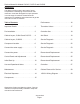
Service Manual for Models CU0415, CU0715 and CU0920 Introduction The design of this product is the result of years of experience in developing commercial ice cube machines. It has been designed for simple operation in a wide range of locations. Please follow the instructions for installation and maintenance to get the most use from this ice machine. Table of Contents Performance . . . . . . . . . . . . . . . . . . . . . . . . 16 Important Details. . . . . . . . . . . . . . . . . . . . .
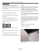
Service Manual for Models CU0415, CU0715 and CU0920 Important Details The machine is designed for use indoors in a controlled environment. It must be kept dry, not overheated or subjected to excessive cold. The water and power supply must be maintained or the machine will stop making ice. There are limits to how hot or cold the room it’s in can be. • Minimum air temperature: 50oF or 10oC The warranty statement for this product is provided separately from this manual. Refer to it for applicable coverage.
Service Manual for Models CU0415, CU0715 and CU0920 Pre-Installation Spacing: This appliance is intended to be used in commercial applications including: No additional spacing is required at the top or sides. However, suggested minimum side clearance for installation is 1/8 inch or 3 mm and suggested minimum top clearance is 1/4 inch or 7 mm. • Restaurant kitchens • Bars Allow 4 inches (100 mm) minimum space at the back for the utility connections. Do not block louvers at the front of the cabinet.
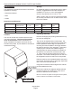
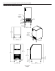
Service Manual for Models CU0415, CU0715 and CU0920 Cabinet Layout, CU0415 and CU0715 POWER CORD POTABLE WATER INLET 1/4" OD. PLASTIC TUBING (5ft) DRAIN 3/4" FPT 14.6cm 5.8in 5.1cm 2.0in 8.2cm 3.2in 34.5cm 13.6in 60.3cm 23.7in POWER CORD POTABLE WATER INLET 1/4" OD. PLASTIC TUBING (5ft) 38.1cm 15.0in DRAIN 3/4" FPT 81.1cm 31.9in 95.4cm 37.6in 68.9cm 27.1in 10.2cm MINIMUM UTILITY CLEARENCE AIR OUTLET AIR INLET 15.2cm 6.0in 29.8cm 11.8in 48.3cm 19.
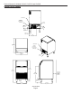
Service Manual for Models CU0415, CU0715 and CU0920 Cabinet Layout, CU0920 POWER CORD POTABLE WATER INLET 1/4" OD. PLASTIC TUBING (5ft) DRAIN 3/4" FPT 14.6cm 5.75in 7cm 2.75in 5.1cm 2.00in 8.2cm 3.23in 32cm 12.60in POWER CORD 60.1cm 23.67in POTABLE WATER INLET 1/4" OD. PLASTIC TUBING (5ft) 50.8cm 20.00in DRAIN 3/4" FPT 81.1cm 31.94in 95.4cm 37.56in 10.2cm 4.00in MINIMUM UTILITY CLEARENCE 68.9cm 27.13in AIR OUTLET AIR INLET 15.2cm 6.00in 42.5cm 16.75in 48.3cm 19.
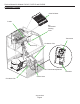
Service Manual for Models CU0415, CU0715 and CU0920 Component Location Cube Deflector Curtain Bin Thermostat Sensing Point Thermostat Condenser Fins Drain Plug Bin Thermostat Adjustment Controller Condenser Fan Control Area August 2013 Page 6
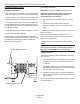
Service Manual for Models CU0415, CU0715 and CU0920 Connect the water supply Connection Information: Plumbing information: WARNING: connect to potable water supply only. • The water supply connection is at the back panel. It is a 5’ (1.5 meter) 1/4 inch (6.35 mm) OD plastic tube. Important: Open the hand water valve to flush water through the connection point before connecting to the ice machine.
Service Manual for Models CU0415, CU0715 and CU0920 Connect the power This is a cord-connected unit, and must be connected to its own dedicated power supply. Check the dataplate on the back of the machine to confirm the voltage and per the dataplate use fuses or HACR circuit breakers. Power Cord: This 115 volt model is equipped with a cord and 5-15P plug. Follow All Local Codes - This Unit Must Be Grounded. Do not use extension cords and do not disable or by-pass ground prong on electrical plug.
Service Manual for Models CU0415, CU0715 and CU0920 Control Panel and Adjustments Ice Bridge Thickness Adjustment Area Ice Bridge Thickness Adjustment Réglage de l'épaisseur du pont de glace Ajuste del espesor del puente de hielo Regolazione spessore ponte di ghiaccio Anpassung der Eisbrückendicke - ON / OFF / WASH MARCHE / ARRÊT / LAVAGE ENCENDIDO / APAGADO / LAVADO ON / OFF / LAVAGGIO EIN / AUS / WASCHEN + + Harvest Time Adjustment Réglage du temps de récolte Ajuste del tiempo de cosecha Regolazione
Service Manual for Models CU0415, CU0715 and CU0920 Initial Start Up 1. Remove the front panel by removing the two screws holding it to the cabinet and pulling the panel down and off the machine. 2. Turn on the water supply, correct any leaks. Note: Water supply MUST be turned on first to allow water to enter the machine properly. 3. Locate the On/Off/Wash master switch. 4. Move the switch to the On position. 5. Ice bridge thickness and harvest time indicator lights will switch on.
Service Manual for Models CU0415, CU0715 and CU0920 Use and Operational Notes To use, simply lift the door by its bottom edge and slide it up and into the top of the machine. Use the scoop to remove ice and close the door. The machine will make the most ice if it has plenty of room to breathe. This is an air cooled product and it must be able to take in room air and discharge air heated by the ice making process.
Service Manual for Models CU0415, CU0715 and CU0920 Maintenance Regularly vacuum the right side of the air cooled condenser with a brush to remove all loose dust and dirt. Be careful not to damage the fins. Cubed ice machines of this type make ice that is more pure than the water supplied to it. Since the ice has fewer impurities, the water that remains in the reservoir has more. The water system dilutes that concentration but eventually it does build up and need to be removed.
Service Manual for Models CU0415, CU0715 and CU0920 7. Drain the reservoir into the storage bin by removing the drain plug. Return the drain plug to its normal position. 8. Wash all interior surfaces of the ice machine storage bin, reservoir surface and inside of the door with the remaining sanitizer solution. 9. Pour any excess sanitizer down the ice machine bin drain. 10. Pour 2.5 quarts or 2.4 liters of warm (95oF/35oC to 115oF./46oC) water into the reservoir by adding it at the reservoirs’ front lip.
Service Manual for Models CU0415, CU0715 and CU0920 Electrical Sequence Proper voltage must be supplied and the bin thermostat closed and calling for ice or the control system will not have power. Initial power up: Moving the master switch from OFF to ON starts the machine in a harvest mode, the compressor is operating with the inlet water solenoid valve and the hot gas valve energized, water enters the machine at the top of the evaporator, flowing down into the reservoir.
Service Manual for Models CU0415, CU0715 and CU0920 Components Sensors: Thermistor for suction line temperature, Thermistor for reservoir water temperature. Compressors, three capacities Type: Hermetic Brand: Embraco Condenser: air cooled forced draft, copper and aluminum. Evaporator: Nickel plated copper, inverted grid Ice: Medium / Full Dice cube. 5 x 9 per cycle, about 1 lb per cycle Evaporator Thermistor Metering device: Capillary tube Mounted above accumulator, clipped to suction line.
Service Manual for Models CU0415, CU0715 and CU0920 Performance CU0415 Compressor amp draw, 115 volt • Freeze, 5 minutes in: 1.8 to 1.9 • Overall Freeze cycle amps, begin at 1.9 decline to 1.7. • Harvest: 1.9 - 1.8 Compressor dome is normally warm. Drain water per cycle at standard harvest setting: about 1.4 quarts, at shorter setting drain water reduced to 1 quart.* CU0715 Compressor amp draw, 115 volt • Freeze, 5 minutes in: 2.6 • Overall Freeze cycle amps, begin at 2.7 decline to 2.5 • Harvest: 2.
Service Manual for Models CU0415, CU0715 and CU0920 Thermistor Values Deg. F Ohms Deg. F Ohms Deg. F Ohms Deg. F Ohms Deg.
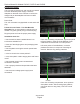
Service Manual for Models CU0415, CU0715 and CU0920 Controller Use When in a Freeze cycle or mode, a blue light will glow. The upper line of LED lights are indictions of the adjustment for Bridge Thickness. More lights = more freeze time and a bigger bridge. The lower level line of LED lights are indicators of the adjustment for Harvest Time. More lights = more harvest time and more water rinse. Unit in ice making mode, freeze mode indicator light is on.
Service Manual for Models CU0415, CU0715 and CU0920 Anti-Slush Slush in the reservoir restricts pump flow, causes excessively long freeze cycles and is something this machine is designed to prevent. It does that by shutting off the water spray to the evaporator at a critical time. The critical time is when the water temperature is near the freezing point. The controller measures the water temperature using a thermistor probe in the pump discharge hose.
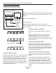
Service Manual for Models CU0415, CU0715 and CU0920 Controller Self Test Control Board Self-Test Routine. Begin with unit unplugged and no ice touching the bin control. 1. Remove top and back panels to access thermistor on suction line (above accumulator). 12. Press and hold lower left - button and it will turn on each of the green LEDs, one at a time. Hold lower left – button in until all of the green LEDs are tested. 2. Remove the thermistor probe from the suction line. 13.
Service Manual for Models CU0415, CU0715 and CU0920 Service Diagnosis Problem Possible Cause Probable Correction No ice No water to ice machine Check water filters, check water pressure. Pressure lower than 10 psi flowing may not fill reservoir enough. No ice, nothing operating No power to ice machine Check power, restore if needed. Open contacts in bin thermostat Check cabinet temperature, thermostat will be open if cabinet is too cold. Advise user to operate unit in proper conditions.
Service Manual for Models CU0415, CU0715 and CU0920 Service Diagnosis Problem Possible Cause Probable Correction No ice, fan motor not turning No power to it Check controller Freeze NO terminal to COM for proper voltage. If blue freeze light is on and no voltage, replace controller Check fan pressure control, if air temperature is over 70 degrees F, the pressure control should be closed when in freeze mode.
Service Manual for Models CU0415, CU0715 and CU0920 Service Diagnosis Problem Possible Cause Makes ice but makes blocks or shells Ice bridge wrong size Probable Correction Adjust to proper size Evaporator thermistor out of calibration, adjustment erratic Check thermistor resistance to chart, replace if incorrect Poor thermal contact of evaporator thermistor to suction line Check clip holding probe, must have metalto-metal contact and covered with insulation Thermistor failure, unit operating on time
Service Manual for Models CU0415, CU0715 and CU0920 Removal and Replacement Curtain Top Edge Curtain 1. Remove front panel and switch unit Off. 2. Remove top panel. 3. Remove evaporator cover. 4. Locate white curtain top at front of evaporator, pull up on it and remove from the unit. 5. Slide new curtain down in same place as original, into the slot between the plastic evaporator frame and the front of the reservoir. Push curtain down into the slot as far as it will go. 6.
Service Manual for Models CU0415, CU0715 and CU0920 Removal and Replacement Pump Wall Panel 1. Disconnect electrical power. 2. Remove top panel. 3. Remove wall panel covering pump. 4. Disconnect wires from pump motor. 5. Remove cube deflector and pull hose off water pump outlet. 6. Rotate pump slightly CW and lift pump up and out of the ice machine. 7. Install new pump in reverse order of the removal steps. Spray Platform 1. Remove front panel. 2. Shut unit off. 3.
Service Manual for Models CU0415, CU0715 and CU0920 Removal and Replacement 3. Remove front panel. Bin Thermostat 4. Remove top panel. 1. Disconnect electrical power. 5. Remove right side panel. 6. Remove back panel. Electrical Shock Hazard Disconnect electrical power before beginning 7. Shut water off to unit. 8. Remove utility panel, lower left corner viewed from the back. Valve bracket is attached to panel. 9. Locate inlet water solenoid valve. 2. Remove front panel. Collet 3.
Service Manual for Models CU0415, CU0715 and CU0920 Controller The controller ships set for CU0715 and must be adjusted for other models. Please review these instructions prior to installation. 1. Disconnect electrical power. 2. Remove front panel. 3. Remove control box back cover 4. Disconnect all wires from controller, squeeze standoffs together to release from bracket and remove controller from the ice machine. 5.
Service Manual for Models CU0415, CU0715 and CU0920 Cabinet Removal for Service 1. Remove front panel. 2. Remove top panel. Remove 3. Remove door. 4. Drain water from reservoir. 5. Disconnect water and drain and electrical power. 6. Remove back and side panels. 7. Pull bin thermostat cap tube from tube in bin. 8. Remove evaporator cover. Remove Evaporator Screws 9. Remove screws holding evaporator to its frame, lift evaporator up out of the way.
3 OVERLOAD August 2013 Page 29 THIS UNIT MUST BE GROUNDED * SEE NAMEPLATE FOR PROPER VOLTAGE REQUIREMENTS AND MAXIMUM FUSE SIZE POWER IN 1 M RELAY - CURRENT GN/Y EARTH GROUND B/W COMPRESSOR W W or BN GN/Y BK or BL B/W 6 4 1 OFF 2 3 ON WASH 3-WAY SWITCH 5 B/W W FUSE (3A) (50Hz only) BN/W BU BU/W FREEZE NO AC PWR COM R HARV NC ELECTRONIC CONTROL PUMP COM 12V BU PUMP NC GND 12V CAUTION: MORE THAN ONE DISCONNECT MEANS MAY BE REQUIRED TO DISCONNECT ALL POWER TO UNIT CO
SCOTSMAN ICE SYSTEMS 775 Corporate Woods Parkway Vernon Hills, IL 60061 USA 847-215-4500 800-726-8762 www.scotsman-ice.