
Technical Guide

Page 5
New Eclipse Technical Review
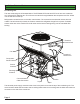
The ice making head contains one or two evaporators, each with its own TXV and vapor inlet valve. The
control system is also located there as are the pump, inlet water solenoid valve and purge valve.
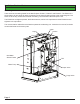
The condensing unit contains most of the refrigeration components, including the compressor, condenser, fan
motor, crankcase pressure regulating valve, receiver, accumulator, headmaster, condenser bypass valve and
liquid inlet valve.
A communication cable connects the controller and two relays in the ice making head to the contactor and
solenoid valves in the compressor package. The Contactor relay in the head is operated by the controller and
has power during ice making. The Hot Gas Valve relay is powered by the controller only during harvest and
connects power in the condensing unit to the bypass valve and liquid inlet valve.
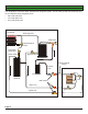
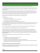
Refrigeration System Operation, refer to the schematic on the opposite page.
During Freeze,
• The compressor is operating.
• The vapor inlet and condenser by pass valves are closed.
• The normally open liquid line inlet valve is open.
• The headmaster is open between condenser inlet and liquid outlet.
Under low ambient/low pressure conditions, the headmaster valve closes the liquid outlet of the condenser and
opens a bypass route to direct refrigerant gas to the receiver inlet until discharge pressure builds back up to
the headmaster’s set point.
From the receiver liquid outlet, liquid refrigerant ows into the liquid line and into the ice making section.
At the ice making section, the refrigerant ows into the three expansion valves.
After the evaporator, low-pressure refrigerant gas ows into the suction line, which carries it back to the
condensing unit, where it enters the accumulator. The accumulator includes a loop of the liquid line inside
the tank, not illustrated in the schematic. In the accumulator most of any liquid carried with the suction gas is
separated and only vapor ows out of the accumulator through the CPR valve and to the compressor where
the cycle continues.
Suction pressure during freeze will be the same at the compressor or at the evaporators.
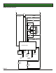
During harvest,
• The bypass and vapor valves are energized and open.
• The liquid inlet valve is energized and closed.
• The side port of the receiver releases high pressure gas into the vapor line.
• The CPR valve limits the compressor dome suction pressure to a pre-set maximum; evaporator pressure
(measured at the suction shut off valve) will be higher.
Refrigerant Recovery and System Evacuation Notice
In the event the refrigerant must be recovered from this system and the system evacuated, recover and
evacuate from the three ball valve access valves.