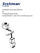
Installation and User Manual for Prodigy Eclipse Cuber model EH222 C with ECC Condensing Unit
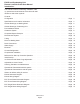
EH222 and Condensing Unit Remote Low Side Cuber User Manual Introduction: This manual covers the assembly, installation, start up, operation and maintenance of the 800 and 1000 remote low side cuber systems. Contents Configuration . . . . . . . . . . . . . . . . . . . . . . . . . . . . . . . . . . . . . . . . . . . . . . Page 3 Specifications and Location Information. . . . . . . . . . . . . . . . . . . . . . . . . . . . . . . . .
EH222 and Condensing Unit Remote Low Side Cuber User Manual Configuration A remote low side cuber system includes two sub systems: an ice making head and a remote air cooled condensing unit. This manual covers the EH222 head and the condensing units that go with it. The ice making heads are designed for use indoors in a controlled environment. The remote condensing units are designed to operate outdoors. Each subsystem has limits for power, water and temperature.
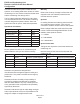
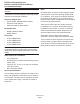
EH222 and Condensing Unit Remote Low Side Cuber User Manual Specifications and Location Information Model Electrical volts/Hz/phase EH222SL-1C ECC0800-32 ECC0800-3 ECC1410-32 115/60/1 208-230/60/1 208-230/60/3 208-230/60/1 Minimum Circuit Ampacity 1.13 14.8 10.6 14.5 Maximum Fuse Size System Charge, oz of R-404A Cabinet Size* w” x d” x h” Unit Weight (lb) 15 20 15 30 shipped w/none 192 192 224 22 x 16.5 x 29 32 x 39 x 39.75 32 x 39 x 39.75 32 x 39 x 39.75 90 224 32 x 39 x 39.
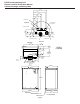
EH222 and Condensing Unit Remote Low Side Cuber User Manual Cabinet Drawings, Ice Making Head 131.70 5.19 115.95 4.57 79.38 3.13 68.20 2.69 42.80 1.69 3/8" LIQUID LINE 24 .95 ELECTRICAL CORD ACCESS HOLE INTERFACE CABLE ACCESS HOLE 1/2" COOL VAPOR LINE 67.56 2.66 34.04 1.34 34.04 1.34 24.89 .98 POTABLE WATER INLET 3/8" 3/4" SUCTION LINE DETAIL A TOP VIEW 482.60 19.00 47.72 1.88 EH222 ICE HEAD 83.82 3.30 82.55 3.25 ICE DROP AREA A 263.65 10.38 76.20 3.00 273.05 10.
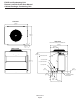
EH222 and Condensing Unit Remote Low Side Cuber User Manual Cabinet Drawings, Condensing Unit TOP VIEW 992.81 39.09 814.22 32.06 SIDE VIEW LINE SET AND ELECTRICAL ATTACHMENT SIDE FRONT VIEW 32.05 1.26 TYP. 330.86 13.03 750.06 29.53 887.73 34.95 .88" ELECTRICAL INLET 1009.65 39.75 3/4" SUCTION LINE 1/2" COOL VAPOR LINE 3/8" LIQUID LINE 83.67 3.29 63.50 2.50 74.12 2.92 INTERFACE HARNESS ACCESS HOLE 163.02 6.42 248.87 9.80 March 2013 Page 6 491.69 19.
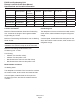
EH222 and Condensing Unit Remote Low Side Cuber User Manual Pre-Installation Details Water Note: The ice making section cannot be stacked vertically. Accessories such as bin adapters and tubing kits are required to complete the installation. Dispenser Adapter Kits: • • • ornelius ABS: KBTABS ED150: KBT40 C Scotsman ID150: KBT40 Scotsman ID200 or ID250: KBT41 There are two ways water can contain impurities: in suspension or in solution. Suspended solids can be filtered out of the water.
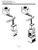
EH222 and Condensing Unit Remote Low Side Cuber User Manual Create the System Plan the installation. The system consists of three parts: the ice making head, the condensing unit and the interconnecting tubing. Of these, the biggest variable is the interconnecting tubing. Tubing: The tubing consists of three insulated and sealed soft copper tubes. One tube, the liquid line, is 3/8” OD. The vapor tube is ½” OD and the suction tube is ¾” OD.
EH222 and Condensing Unit Remote Low Side Cuber User Manual Completed System Example March 2013 Page 9
EH222 and Condensing Unit Remote Low Side Cuber User Manual Place Remote System Roof preparation Roof Pipe Curb or Pitch Pocket: Most installations of this system will place the condensing unit on the roof of a building. The roof must be physically able to accept the load of the equipment and the roofing material must be prepared to prevent water leaks. To avoid potential kinking of the refrigeration tubing, avoid small, tight radius types of covers on pitch pockets.
EH222 and Condensing Unit Remote Low Side Cuber User Manual Tubing The line set must be routed between the condensing unit and the ice maker’s location. During the transition from quick connects to braze connections, the ice maker, condensing unit and line set may or may not have quick connects, use this chart as a guideline for the proper action based on what is available at the site.
EH222 and Condensing Unit Remote Low Side Cuber User Manual Place Ice Making Head Remove from carton. Water and Drain Place adapter kit onto bin or dispenser top. If adapter does NOT have gasket tape install tape such as Scotsman part number 19-0503-04. The adapter to ice head base MUST be sealed with gasket tape or food grade sealant. The ice maker requires an adequate potable water supply and a gravity drain.
EH222 and Condensing Unit Remote Low Side Cuber User Manual Drain Connections Right Draining: Left Draining: Rotate elbow to the other direction. 1. Connect ¾” PVC to the female PVC fitting. If copper is required by code, remove the PVC connector and install a ¾” FPT female copper fitting onto the ¾” NPT male fitting. Do all soldering before connecting to the male fitting. Connect ¾” PVC to the PVC fitting. 2. In tight locations do the next step after the unit is placed on the dispenser or bin. 3.
EH222 and Condensing Unit Remote Low Side Cuber User Manual Water Supply: A 3/8" flare nut on tubing is located at the top panel, near the refrigeration tubing. Inside the hardware bag, inside the cabinet, a 3/8" inch double male flare adapter (flare union) is supplied. Use the supplied adapter to make a 3/8" male flare fitting for the water inlet. Connect a cold, potable water supply to the 3/8” water inlet fitting installed above. Use 3/8" OD copper or other comparable sized tubing for the water supply.
EH222 and Condensing Unit Remote Low Side Cuber User Manual Electrical: Condensing Unit Head Route interconnecting control wire through proper hole end of condensing unit and plug into the connection on the control box. Plug head’s power cord into a nearby 115 volt electrical outlet. Route power conduit (liquid tight) and wires to the junction box of the ECC unit. Secure with the proper type of connector. Note: The power supply wires must be the correct size and type per the National Electric Code.
EH222 and Condensing Unit Remote Low Side Cuber User Manual Connect Refrigeration At Head Requires brazing, steps must be performed by an EPA certified type II or higher technician. 1. With nitrogen flowing from condensing unit, braze the liquid, vapor and suction line connections. At Head: 1. Remove protective plugs from all three connections and vent the nitrogen from the ice machine. 2. Remove refrigeration hose from head. Be sure valve cap is on tight. 3.
EH222 and Condensing Unit Remote Low Side Cuber User Manual Complete the Installation After the utilities and refrigeration connections have been made, secure the unit to the dispenser or bin top. Note: The refrigerant lines above the machine must be able to move freely while the machine is being moved into position. Secure ice making section to dispenser or bin adapter. Final Check List Before Initial Start Up 1. Confirm that the ice making section is installed indoors in a controlled environment.
EH222 and Condensing Unit Remote Low Side Cuber User Manual Reference for Start Up: Controller Operation The controller has four indicator lights, a code display, four push buttons, and eleven component indicator lights.
EH222 and Condensing Unit Remote Low Side Cuber User Manual Initial Start Up Pre Start A soak-out period of four hours is optional for this system. If desired, powering the compressor unit for four hours prior to start up allows the crankcase heater to warm up the oil in the compressor. Start Up 1. Connect power to the condensing unit and move its toggle switch to Run or On. 2. Open the water supply valve. 3. Remove the head’s front panel. Check for any packing or wires rubbing moving parts.
EH222 and Condensing Unit Remote Low Side Cuber User Manual Ice Thickness and Water Purge Adjustment Bridge Thickness - For the Service Tech Only 1/8 to 3/16” Bridge 1. Push and hold Off till the machine stops. 2. Remove evaporator cover. 3. Remove curtain. 4. Use a hex wrench and rotate the bridge thickness adjustment screw in 1/16 turn increments CW to increase bridge thickness. 5. Rotate CCW to decrease bridge thickness.
EH222 and Condensing Unit Remote Low Side Cuber User Manual Adjustable Ice Level Control There is an adjustment post and an additional indicator light to the right of the four indicator lights. The ultrasonic ice level control allows the user to control the point that the ice machine will stop making ice before the bin or dispenser is full.
EH222 and Condensing Unit Remote Low Side Cuber User Manual Cleaning, Sanitation and Maintenance This ice system requires three types of maintenance: • Remove the build up of mineral scale from the ice machine’s water system and sensors. • • Sanitize the ice machine’s water system and the ice storage bin or dispenser. Clean the remote air cooled condenser. It is the User’s responsibility to keep the ice machine and ice storage bin in a sanitary condition.
EH222 and Condensing Unit Remote Low Side Cuber User Manual 20. Return water level sensor, ice thickness sensor, water distributors and curtains to their normal positions. Be sure hose is reattached to water distributor. Be sure all surfaces of the ice thickness sensor are dry. 21. Push and hold the clean button to drain the reservoir. Push and release the clean button again and when the purge valve indicator light goes out, immediately pour the remaining sanitizer solution into the reservoir. 22.
EH222 and Condensing Unit Remote Low Side Cuber User Manual Operational Characteristics 800 lb system Cycle Times @ Condenser Temp/Cabinet Temp/Water Temp in degrees F. 70/70/50 90/90/70 Freeze 10 to 12 minutes 13 to 15 minutes Harvest 1 to 1.5 minutes 1 to 1.
EH222 and Condensing Unit Remote Low Side Cuber User Manual What to do before calling for service: Reasons the machine might shut itself off: • • • • • Lack of water. Freeze cycle takes too long. Harvest cycle takes too long. High discharge pressure. Ice level control set wrong Check the following: 1. Has the water supply to the ice machine or building been shut off? If yes, the ice machine will automatically restart within 25 minutes after water begins to flow to it. 2.
EH222 and Condensing Unit Remote Low Side Cuber User Manual EH222 Schematic Diagram L2 L1 LINE HARVEST ASSIST SOLENOID TRANSFORMER 12V HOT GAS VALVE TO COMPRESSOR SECTION HGV RELAY CONTACTOR RELAY WATER VALVE ELECTRONIC CONTROL WATER LEVEL SENSOR DISCHARGE TEMP. SUMP TEMP.
EH222 and Condensing Unit Remote Low Side Cuber User Manual EH222 Wiring Diagram USE COPPER CONDUCTORS ONLY 1 DASHED LINES INDICATE FIELD WIRING WHICH MUST BE INSTALLED IN ACCORDANCE WITH THE NATIONAL ELECTRICAL CODE AND ALL STATE AND LOCAL CODES.
EH222 and Condensing Unit Remote Low Side Cuber User Manual ECC Three Phase Schematic Diagram March 2013 Page 28
EH222 and Condensing Unit Remote Low Side Cuber User Manual ECC Three Phase Wiring Diagram March 2013 Page 29
EH222 and Condensing Unit Remote Low Side Cuber User Manual ECC Single Phase Schematic Diagram March 2013 Page 30
EH222 and Condensing Unit Remote Low Side Cuber User Manual ECC Single Phase Wiring Diagram March 2013 Page 31
SCOTSMAN ICE SYSTEMS 775 Corporate Woods Parkway Vernon Hills, IL 60061 www.scotsman-ice.